Anand K. Verma - Introduction To Modern Planar Transmission Lines
Здесь есть возможность читать онлайн «Anand K. Verma - Introduction To Modern Planar Transmission Lines» — ознакомительный отрывок электронной книги совершенно бесплатно, а после прочтения отрывка купить полную версию. В некоторых случаях можно слушать аудио, скачать через торрент в формате fb2 и присутствует краткое содержание. Жанр: unrecognised, на английском языке. Описание произведения, (предисловие) а так же отзывы посетителей доступны на портале библиотеки ЛибКат.

- Название:Introduction To Modern Planar Transmission Lines
- Автор:
- Жанр:
- Год:неизвестен
- ISBN:нет данных
- Рейтинг книги:4 / 5. Голосов: 1
-
Избранное:Добавить в избранное
- Отзывы:
-
Ваша оценка:
Introduction To Modern Planar Transmission Lines: краткое содержание, описание и аннотация
Предлагаем к чтению аннотацию, описание, краткое содержание или предисловие (зависит от того, что написал сам автор книги «Introduction To Modern Planar Transmission Lines»). Если вы не нашли необходимую информацию о книге — напишите в комментариях, мы постараемся отыскать её.
rovides a comprehensive discussion of planar transmission lines and their applications, focusing on physical understanding, analytical approach, and circuit models
Planar transmission lines form the core of the modern high-frequency communication, computer, and other related technology. This advanced text gives a complete overview of the technology and acts as a comprehensive tool for radio frequency (RF) engineers that reflects a linear discussion of the subject from fundamentals to more complex arguments.
Introduction to Modern Planar Transmission Lines: Physical, Analytical, and Circuit Models Approach Emphasizes modeling using physical concepts, circuit-models, closed-form expressions, and full derivation of a large number of expressions Explains advanced mathematical treatment, such as the variation method, conformal mapping method, and SDA Connects each section of the text with forward and backward cross-referencing to aid in personalized self-study
is an ideal book for senior undergraduate and graduate students of the subject. It will also appeal to new researchers with the inter-disciplinary background, as well as to engineers and professionals in industries utilizing RF/microwave technologies.
Introduction To Modern Planar Transmission Lines — читать онлайн ознакомительный отрывок
Ниже представлен текст книги, разбитый по страницам. Система сохранения места последней прочитанной страницы, позволяет с удобством читать онлайн бесплатно книгу «Introduction To Modern Planar Transmission Lines», без необходимости каждый раз заново искать на чём Вы остановились. Поставьте закладку, и сможете в любой момент перейти на страницу, на которой закончили чтение.
Интервал:
Закладка:
where ξ 2/με is nearly unity. The magnetoelectric coupling parameters ξ and ζ have two components: the chirality parameter κ ( kappa ) and the cross‐coupling parameter χ ( chi ). The chirality parameter κ measures the degree of the handedness of the medium. The parameter χ is due to the cross‐coupling of fields. It decides the reciprocity (χ = 0) and nonreciprocity (χ ≠ 0) of the medium, giving the reciprocal and nonreciprocal material medium, respectively. In absence of cross‐coupling, i.e. χ = 0, the parameters ξ and ζ are reduced to imaginary quantities, and the bi‐isotropic medium is reduced to a nonchiral simple isotropic medium for κ = 0 and to a chiral medium for κ ≠ 0. It is also known as Pasteur medium . It supports the left‐hand and right‐hand circularly polarized waves as the normal modes of propagation. It is a reciprocal medium. For κ = 0, χ ≠ 0 another medium, called Tellengen medium , is obtained. It is a nonreciprocal medium. The general bi‐isotropic medium has χ ≠ 0, κ ≠ 0. It is a nonreciprocal medium.
The gyrotropic medium and bianisotropic medium support left‐hand and right‐hand circularly polarized EM‐waves. However, there is a difference. The gyrotropic medium supports the Faraday rotation, i.e. rotation of linearly polarized wave while propagating in the medium, whereas bianisotropic medium does not support it [B.21].
4.2.4 Nondispersive and Dispersive Medium
The medium in which the EM‐wave propagates with equal phase velocity at all frequencies is called the nondispersive medium. For such a medium, the relative permittivity and relative permeability are real quantities, and they are independent of frequency. However, practically every material medium has losses; and thus their relative permittivity and relative permeability are complex quantities, and these are a function of frequency. Thus, normally a material medium supports frequency‐dependent phase velocity. Such a medium is called the dispersive medium . This kind of dispersion is known as material dispersion [B.2, B.3, B.9, B.10]. The material dispersion in the microwave and the mm‐wave ranges is normally negligible for the substrates used in the planar technology. However, a composite substrate , made of the layered dielectric media, is dispersive. Likewise, the artificial metamaterial substrate is also dispersive. The plasma and conducting media are also dispersive in the microwave range. The material dispersion is an important phenomenon near the optical frequency. The constitutive relation for the dispersive medium is
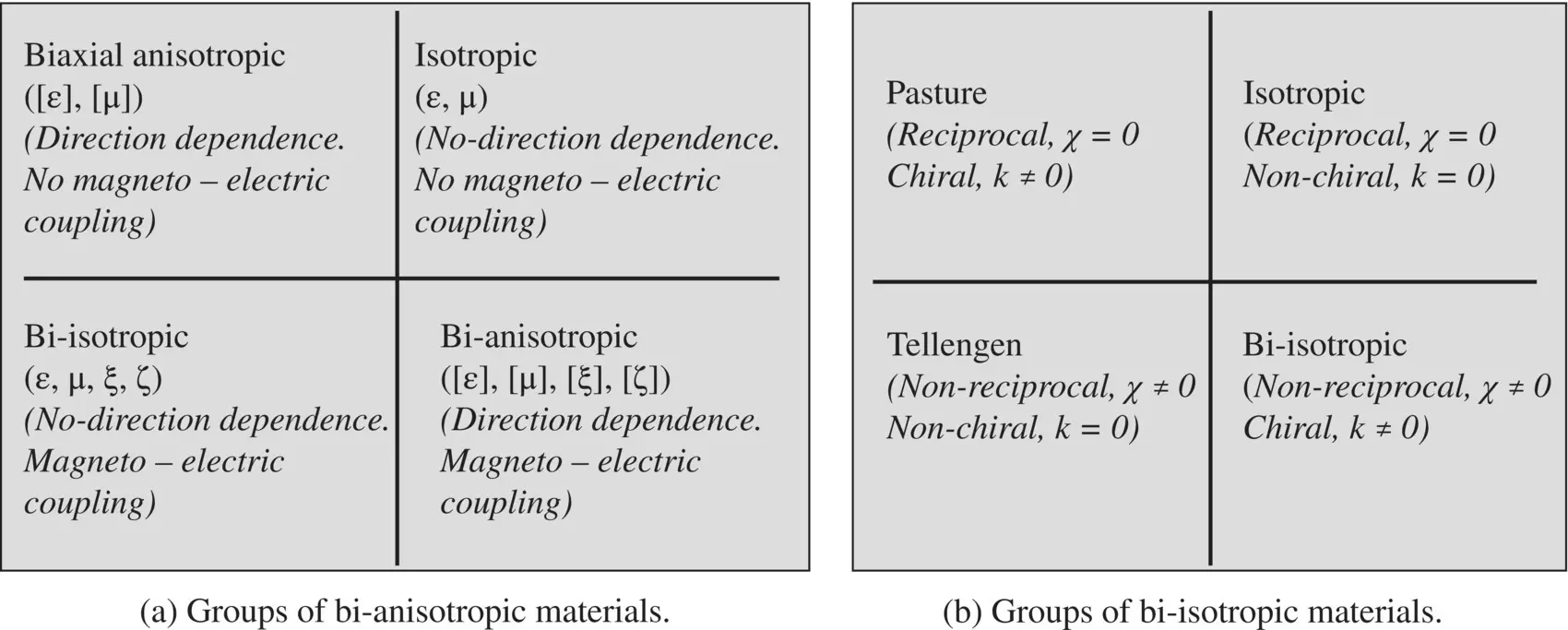
Figure 4.5 Classification of bianisotropic and bi‐isotropic materials.
(4.2.17) 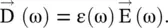
Lorentz oscillator model of a dielectric material, discussed in section (6.5) of chapter 6, helps to understand the frequency‐dependent origin of the ε(ω). When an EM‐pulse, like a Gaussian pulse, passes through a dispersive medium, its pulse‐width widens due to the separation of different frequency components, as each frequency component travels at a different velocity in the dispersive medium. This is known as the pulse‐spreading phenomenon. It limits the speed of digital data transmission through the dispersive medium, as the digital bits can overlap each other. However, a dispersive medium can be nonlinear also, where the pulse spreading can be balanced by the nonlinearity. Under such combined dispersion, and nonlinearity, a pulse can propagate without changing its shape. Such robust EM‐waves are called the solitons . The solitons are useful in optical communication. However, the solitons have also been generated in the microwaves frequency range
4.2.5 Non‐lossy and Lossy Medium
All physical dielectric and magnetic material media have some amount of loss. Normally, the substrates used in the microwave planar technology do not have a high loss, except the doped semiconducting substrates. The lossy dielectrics are known as the imperfect dielectrics . The losses in the dielectric and magnetic materials change the relative permittivity and permeability into complex quantities:
(4.2.18) 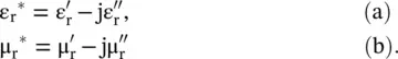
The imaginary parts of the relative permittivity and permeability are taken as negative quantities due to our choice of time‐harmonic function e jωt. However,  and
and  are always positive quantities in a passive lossy medium. The lossy capacitor and the lossy inductor can model the complex relative permittivity and permeability of a medium. This is called the circuit modeling of a material medium . The modeling of the relative permittivity of a medium by the capacitor shows that both the medium and capacitor can store electric energy. Likewise, the relative permeability of medium and the corresponding inductor model both are the magnetic energy storage components.
4.2.6 Static Conductivity of Materials
Figure (4.6a)shows a cylindrical section of the lossy material of conductivity (σ), i.e. resistivity ρ = 1/σ. Its cross‐sectional area and length are A and h, respectively. The lossy material can be modeled as a resistor R, also shown in Fig. (4.6a). The conduction current density J cflowing through the conductor, due to the free mobile charges, is J c= I c/A ,where conduction current is I c= V/R. The electric field intensity in the material is  . On combining these expressions, the following relation is obtained:
(4.2.19) 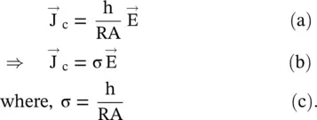
The above expression (4.2.19b)is Ohm's law for a lossy medium. The following expression of the equivalent resistance of a lossy material, in terms of its resistivity, follows from the above equation (4.2.19c):
(4.2.20) 
In general, the Ohm’s law for the anisotropic medium is written in the vector form as  . Further, the expression is also obtained below for the conductivity σ of the material in terms of the basic parameters of mobile charges in a lossy material, i.e. in terms of electron charge and its mobility. The expression is also applicable to semiconductors. In the case of a semiconductor, the conduction current is due to both the electrons (negative charges) and holes (positive charges).
Интервал:
Закладка:
Похожие книги на «Introduction To Modern Planar Transmission Lines»
Представляем Вашему вниманию похожие книги на «Introduction To Modern Planar Transmission Lines» списком для выбора. Мы отобрали схожую по названию и смыслу литературу в надежде предоставить читателям больше вариантов отыскать новые, интересные, ещё непрочитанные произведения.


Обсуждение, отзывы о книге «Introduction To Modern Planar Transmission Lines» и просто собственные мнения читателей. Оставьте ваши комментарии, напишите, что Вы думаете о произведении, его смысле или главных героях. Укажите что конкретно понравилось, а что нет, и почему Вы так считаете.