Magma Redox Geochemistry
Здесь есть возможность читать онлайн «Magma Redox Geochemistry» — ознакомительный отрывок электронной книги совершенно бесплатно, а после прочтения отрывка купить полную версию. В некоторых случаях можно слушать аудио, скачать через торрент в формате fb2 и присутствует краткое содержание. Жанр: unrecognised, на английском языке. Описание произведения, (предисловие) а так же отзывы посетителей доступны на портале библиотеки ЛибКат.
- Название:Magma Redox Geochemistry
- Автор:
- Жанр:
- Год:неизвестен
- ISBN:нет данных
- Рейтинг книги:5 / 5. Голосов: 1
-
Избранное:Добавить в избранное
- Отзывы:
-
Ваша оценка:
Magma Redox Geochemistry: краткое содержание, описание и аннотация
Предлагаем к чтению аннотацию, описание, краткое содержание или предисловие (зависит от того, что написал сам автор книги «Magma Redox Geochemistry»). Если вы не нашли необходимую информацию о книге — напишите в комментариях, мы постараемся отыскать её.
Magma Redox Geochemistry
Volume highlights include: Magma Redox Geochemistry
The American Geophysical Union promotes discovery in Earth and space science for the benefit of humanity. Its publications disseminate scientific knowledge and provide resources for researchers, students, and professionals.
Magma Redox Geochemistry — читать онлайн ознакомительный отрывок
Ниже представлен текст книги, разбитый по страницам. Система сохранения места последней прочитанной страницы, позволяет с удобством читать онлайн бесплатно книгу «Magma Redox Geochemistry», без необходимости каждый раз заново искать на чём Вы остановились. Поставьте закладку, и сможете в любой момент перейти на страницу, на которой закончили чтение.
Интервал:
Закладка:
in which oxidation numbers and then formal charges of involved atoms do not vary.
In ore geochemistry, but also in metallurgical practice, a special mention must be made to redox mechanisms involving chalcophile elements and sulfide. Most often, relevant equilibria are written without the involvement of the medium in which they actually occur. Pyrite formation can result from the hydrothermal alteration of igneous pyrrhotite, but their equilibrium can be simply written in the sole Fe–S system as (Barton, 1970):
(1.10) 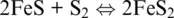
In the Fe–S system, pyrite is not at the liquidus (pyrite does not melt), but as a conceptual exercise we can still relate its formation to the occurrence of the following fictitious half‐reactions in the solid phase involving sulfide and polysulfide anions:
(1.11) 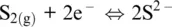
(1.12) 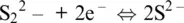
and their combination with iron, which appears in its cationic form Fe 2+in both sides of Reaction 1.10. In the liquid state, melts in which sulfide is the main or the sole anionic ligand are very scarcely represented on Earth and segregate from reducing sulfur oversaturated magmatic silicate melts (e.g., Li and Ripley, 2013 and references therein). Instead, sulfide melts are of interest in extractive metallurgy (e.g., Sokhanwaran et al., 2016).
1.1.2. The Redox Potential in Solutions and the Ligand Role
In redox reactions a potential difference drives the transfer electrons from an anode (negative electrode) to a cathode (positive electrode): oxidation occurs at the anode and reduction occurs at the cathode. Reactions are spontaneous in the direction of ΔG < 0, which is also the direction in which the potential (defined as E cathode– E anode) is positive. In a redox reaction the anode is then the half‐reaction written with electrons on the right and the cathode is the half‐reaction with electrons appearing on the left side.
The electric work done by a spontaneous redox reaction, like in a galvanic cell (E > 0), is the (measurable) electromotive force of the reacting systems and equals the Gibbs free energy change (e.g. Ottonello, 1997) via the Nernst equation:
(1.13) 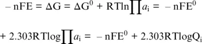
with a ithe activity of the i thcomponent participating in the redox exchange, F as the Faraday constant (96,485 Coulomb per mole), n the number of transferred electrons, and Q the activity product. In writing redox reactions, complete electrolytes are often used because the activity coefficients are measured without extra thermodynamic assumptions, but Equation 1.13is normally used for reactions based on individual ions. To establish a potential scale for half‐reactions, we keep using the convention that electrons are reported on the left‐hand side of the reaction, that is, in the sense of reduction. The potentials of half‐reactions can be added and subtracted, like free energies, to give an overall value for the reaction. It is also worth noting that by convention, it was decided to use a hydrogen‐electrode‐scale electric potential, by setting E 0= 0.0 V for reaction 1.7with the constituents in their standard state (e.g., Casey, 2017). This arbitrary decision implies that (i) the Gibbs energy for H + (aq), the electron (e –), and H 2(g)are all 0.0 kJ/mol, and (ii) potential difference of reactions involving the hydrogen electrode (Reaction 1.7) are given by the other half‐reaction completing the redox exchange.
The electrode potential values (E 0) hold at standard conditions: by definition, standard conditions mean that any dissolved species have concentrations of 1 m, any gaseous species have partial pressures of 1 bar, and the system is 25°C. Standard potentials represent the case where no current flows and the electrode reaction is reversible. Measuring a voltage is an indication that the system is out of equilibrium. Nernstian processes are characterized by fast electron transfer and are rate‐limited by the diffusion of the electron‐active species into the electrolyte. The system then spontaneously approaches equilibrium because negative and positive charged species can flow in opposite directions. At equilibrium, the voltage drops to zero and the current stops, like in dead batteries. The magnitude of the cell potential, E 0= E 0 cathode– E 0 anode, may be viewed as the driving force for current flow in the circuit.
The hydrogen‐electrode scale electric potential so defined, E (also indicated as E hin aqueous solutions), is a measure of the oxidation state of a system at equilibrium relative to a hydrogen electrode. E is not a constant (for given T and P) but depends on the system composition via activities of ions entering a half redox reaction. When coupled to a compositional parameter of the system related to the activity of the ligand making up the solvent of interest, such as a H+ for aqueous solutions, E can be used to establish a kind of phase diagram that shows which species (dissolved ion species, gases, or solids) will predominate among a chosen set in the system of interest (a solution) for a given temperature.
To easily understand all this, we can look at the reaction leading to the formation of liquid water:
(1.14) 
which is given by the sum of Reaction 1.7(H +/H 2redox couple: the anode) and the following half‐reaction (the cathode):
(1.15) 
which is governed by the O 2/H 2O redox couple. The presence of protons in both Reactions 1.7and 1.15shows that the overall Reaction 1.14is defined for acidic conditions (pH < 7). For neutral or basic conditions (pH ≥ 7), Reaction 1.14can be obtained from the following two half‐reactions for H 2O/H 2and O 2/OH –couples, respectively:
(1.16) 
(1.17) 
Let us now deal with Reactions 1.7and 1.15occurring in the acidic medium (see, for example, Ottonello, 1997). The standard potential of Reaction 1.15is E 0 16= 1.228 V and refers to a standard state of water in equilibrium at T = 25°C and P = 1 bar with an atmosphere of pure O 2. From Equation 1.13we obtain:
(1.18) 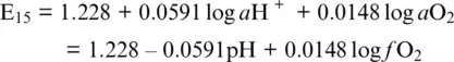
where a and f denote activity and fugacity, respectively, pH = –log a H+ and it is considered that a O 2= f O 2/ f O 2 0with f O 2 0= 1 bar.
Читать дальшеИнтервал:
Закладка:
Похожие книги на «Magma Redox Geochemistry»
Представляем Вашему вниманию похожие книги на «Magma Redox Geochemistry» списком для выбора. Мы отобрали схожую по названию и смыслу литературу в надежде предоставить читателям больше вариантов отыскать новые, интересные, ещё непрочитанные произведения.


Обсуждение, отзывы о книге «Magma Redox Geochemistry» и просто собственные мнения читателей. Оставьте ваши комментарии, напишите, что Вы думаете о произведении, его смысле или главных героях. Укажите что конкретно понравилось, а что нет, и почему Вы так считаете.