Active Electrical Distribution Network
Здесь есть возможность читать онлайн «Active Electrical Distribution Network» — ознакомительный отрывок электронной книги совершенно бесплатно, а после прочтения отрывка купить полную версию. В некоторых случаях можно слушать аудио, скачать через торрент в формате fb2 и присутствует краткое содержание. Жанр: unrecognised, на английском языке. Описание произведения, (предисловие) а так же отзывы посетителей доступны на портале библиотеки ЛибКат.
- Название:Active Electrical Distribution Network
- Автор:
- Жанр:
- Год:неизвестен
- ISBN:нет данных
- Рейтинг книги:5 / 5. Голосов: 1
-
Избранное:Добавить в избранное
- Отзывы:
-
Ваша оценка:
Active Electrical Distribution Network: краткое содержание, описание и аннотация
Предлагаем к чтению аннотацию, описание, краткое содержание или предисловие (зависит от того, что написал сам автор книги «Active Electrical Distribution Network»). Если вы не нашли необходимую информацию о книге — напишите в комментариях, мы постараемся отыскать её.
Discover the major issues, solutions, techniques, and applications of active electrical distribution networks with this edited resource Active Electrical Distribution Network: A Smart Approach
Active Electrical Distribution Network: A Smart Approach
Active Electrical Distribution Network — читать онлайн ознакомительный отрывок
Ниже представлен текст книги, разбитый по страницам. Система сохранения места последней прочитанной страницы, позволяет с удобством читать онлайн бесплатно книгу «Active Electrical Distribution Network», без необходимости каждый раз заново искать на чём Вы остановились. Поставьте закладку, и сможете в любой момент перейти на страницу, на которой закончили чтение.
Интервал:
Закладка:
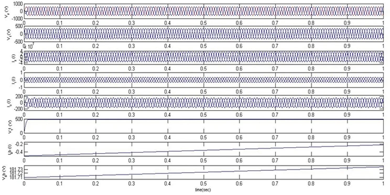
Figure 4.5 Response of DSTATCOM-BESS under a balanced linear load.
4.5.2 Response of DSTATCOM-BESS under a Nonlinear Load
The response of the DSTATCOM-BESS system with the nonlinear load is depicted in Figure 4.6. It has been visualized that the ICCT is initially fixed in the constant current control mode operation. Hence, the system’s other load is removed in order to demonstrate the off-peak condition and under this condition, batteries are now starting to charge. Also, due to efficient control, the reference voltage is regulated in order to maintain a constant charging current. It has also been seen that the DSTATCOM provides a compensating current to maintain the source current and voltage sinusoidal and is balanced by keeping the terminal voltage at its calculated reference voltage. Moreover, the source current harmonics and load current harmonics are illustrated in Figures 4.7 and 4.8 and are visualized at 0.44% and 30.31%, respectively, which shows the proposed system’s superiority.
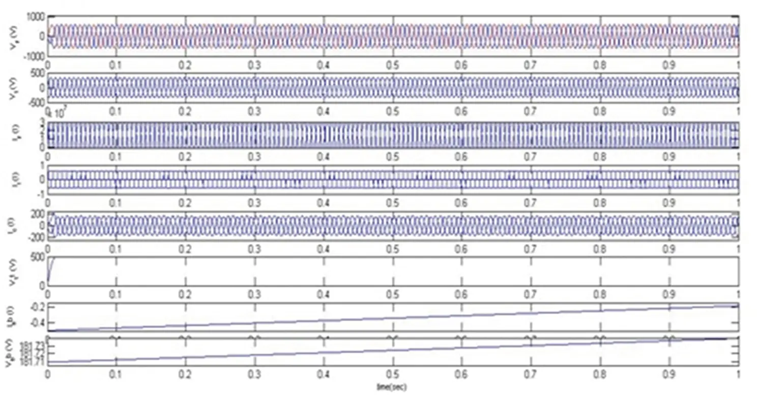
Figure 4.6 Response of DSTATCOM-BESS under a nonlinear load.
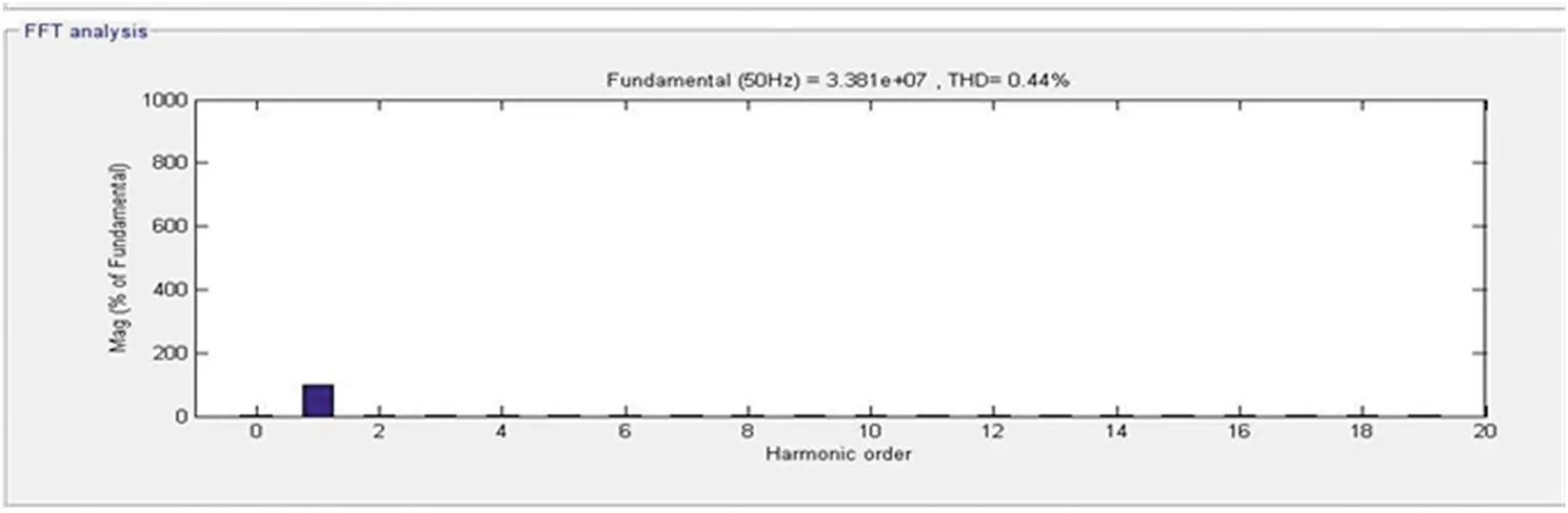
Figure 4.7 Source side frequency spectrum.
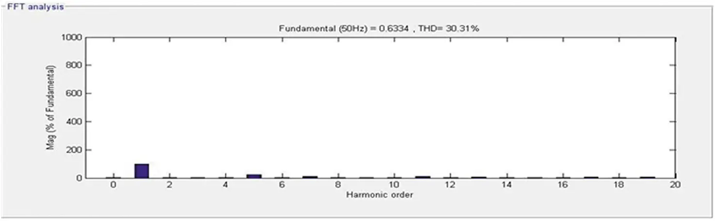
Figure 4.8 Load side frequency spectrum.
4.5.3 Response of DSTATCOM-BESS under an Induction Motor (IM) Load
The response of the DSTATCOM-BESS system with an IM load is as depicted in Figure 4.9. It is well known that if Tm is positive, the machine operates as a motor, and if it is negative, the machine operates as a generator. Hence, the sign of the mechanical torque directs the mode of operation. It has been visualized that the motor takes a large starting current at the time of starting. Accordingly, DSTATCOM injects the compensating current to maintain the voltage at PCC and current sinusoidal. During this condition, the terminal voltage is also kept at its reference voltage and the battery starts charging. Also, the grid side and load side harmonics are depicted in Figures 4.10 and 4.11, respectively. The obtained harmonics are well below the international standard IEEE519-2014. Moreover, Table 4.1illustrates the harmonics-based comparative analysis of all considered loads. The perceived results establish the performance of the DSTATCOM-BESS system.
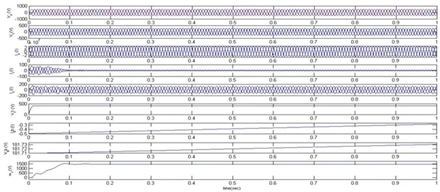
Figure 4.9 Response of DSTATCOM-BESS under an induction motor load.
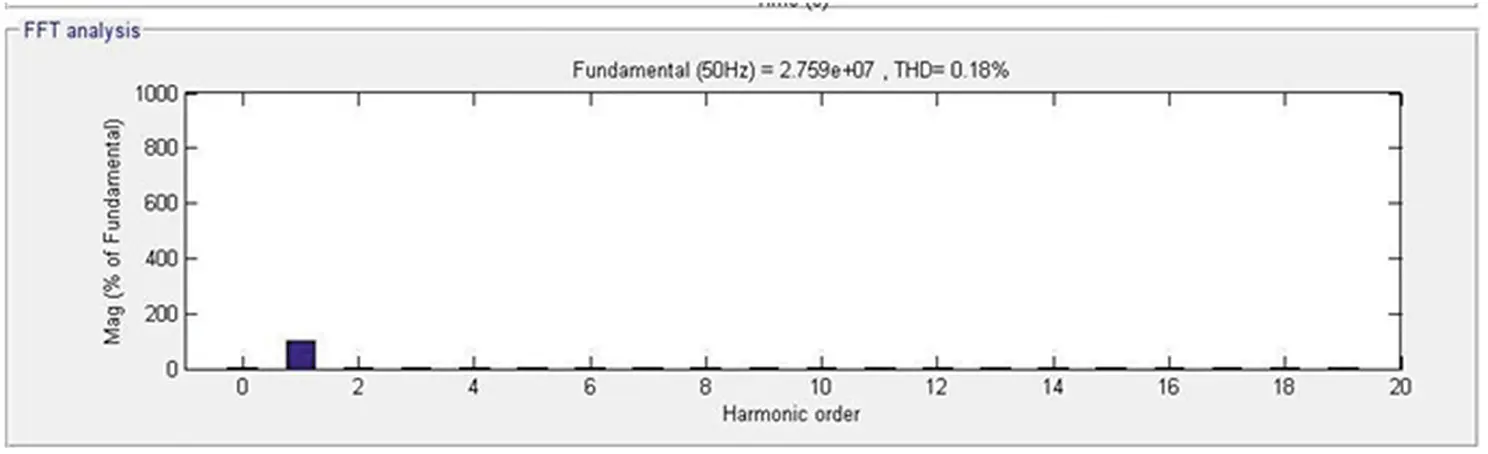
Figure 4.10 Source side frequency spectrum.
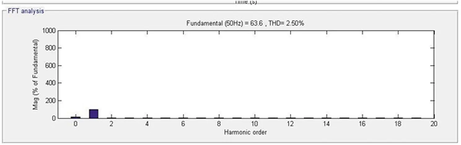
Figure 4.11 Load side frequency spectrum.
Table 4.1 Harmonics analysis under balanced loads.
| S. No. | Type of load | Indirect current control theory controlled DSTATCOM-BESS | |
|---|---|---|---|
| Source side THD | Load side THD | ||
| 1 | Linear load | 0.57% | 0.57% |
| 2 | Nonlinear load | 0.44% | 30.31% |
| 3 | Motor load | 0.18% | 2.50% |
4.6 Results Analysis under an Unbalanced System
4.6.1 Response of DSTATCOM-BESS under an Unbalanced Linear Load
The response of the DSTATCOM-BESS system with an unbalanced linear load is as depicted in Figure 4.12. The unbalancing in the linear load starts from 0.25 seconds to 0.5 seconds. The intention of load unbalancing ( I l) from three-phase to two-phase and then to one-phase and again reverse illustrates the proposed BESS-based system’s performance. It has been perceived that the source voltage ( Vs ) and current ( Is ) are balanced and in-phase during and after the unbalancing. The battery charging is slightly disturbed during unbalancing but maintains a continuous charge ( I b b ). The whole operation compensates the current ( I c) from the DSTATCOM continuously injected while keeping the balanced terminal voltage ( Vt ) at its calculated reference voltage. Also the source and load side current are visualized in Figures 4.13 and 4.14.
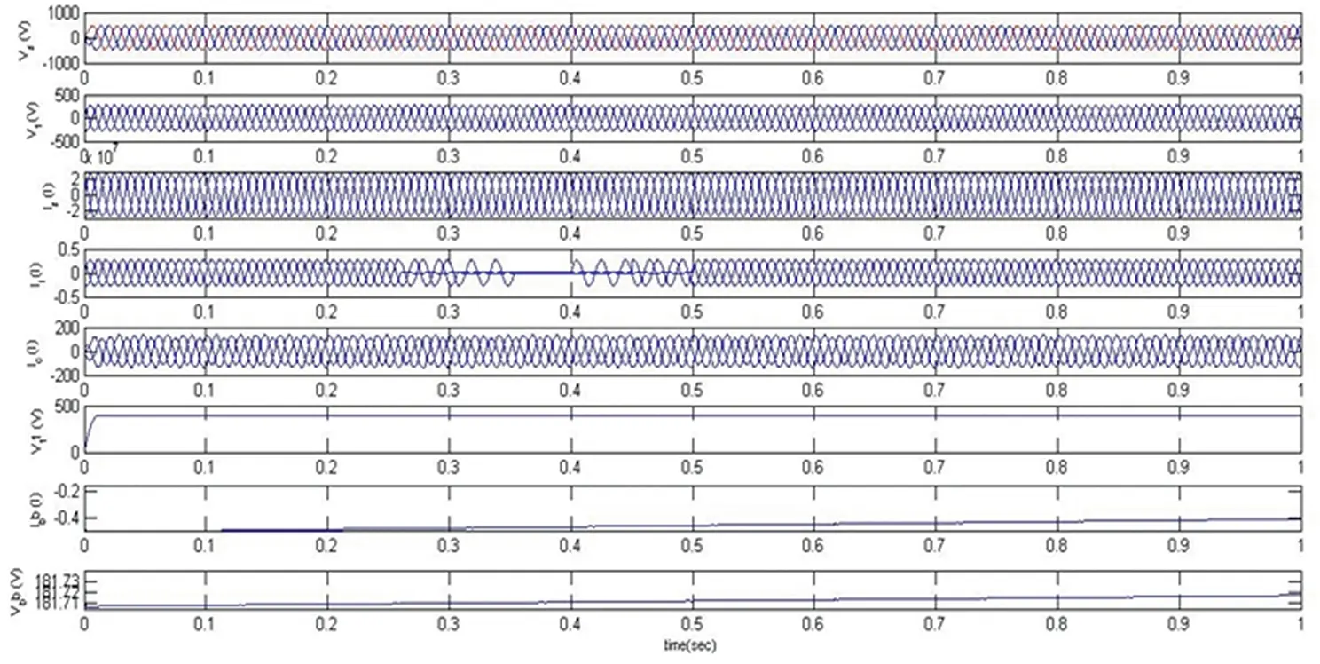
Figure 4.12 Response of DSTATCOM-BESS under an unbalanced linear load.
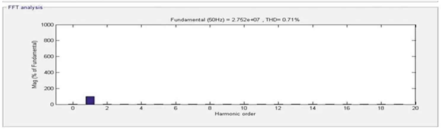
Figure 4.13 Source side frequency spectrum.

Figure 4.14 Load side frequency spectrum.
4.6.2 Response of DSTATCOM-BESS under an Unbalanced Nonlinear Load
The response of the DSTATCOM-BESS system with an unbalanced nonlinear load is as depicted in Figure 4.15. At 0.25 seconds, the three-phase load is transformed to two-phase, and at 0.3 seconds, one-phase and loads are disconnected at 0.35 seconds. The d component of currents is fixed at 35 A. The proposed BESS system supports load levelling and balancing during these loading conditions. The connected nonlinear load is again connected in the same sequence at 0.4, 0.45, and 0.5 seconds. It has been seen that the DSTATCOM provides a compensating current to maintain the source current and voltage sinusoidal and is balanced when keeping the terminal voltage at its calculated reference voltage. Moreover, the source current harmonics and load current harmonics are illustrated in Figures 4.16 and 4.17 and are visualized at 0.19% and 30.31%, respectively, which shows the proposed system’s superiority.
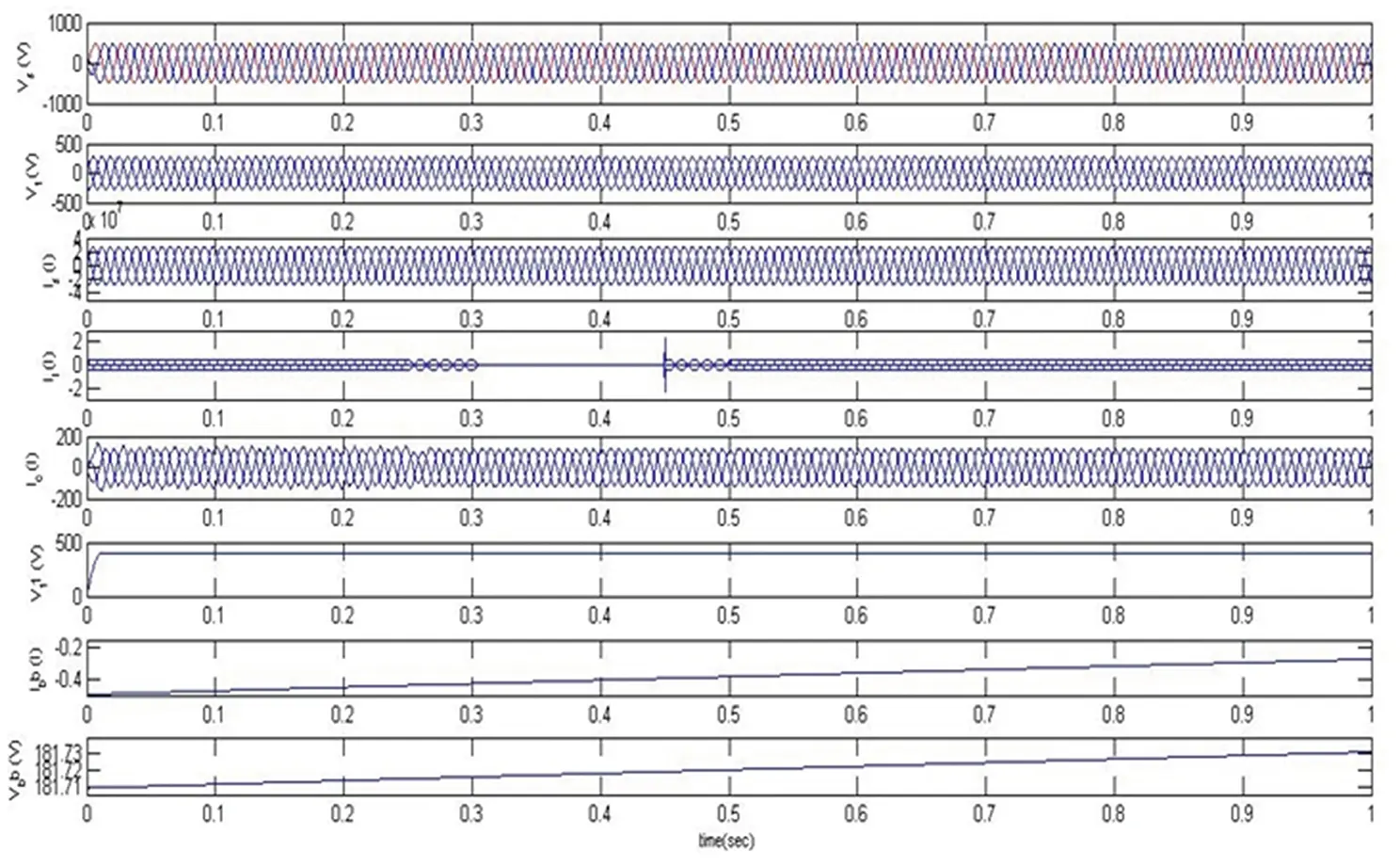
Figure 4.15 Response of DSTATCOM-BESS under an unbalanced nonlinear load.
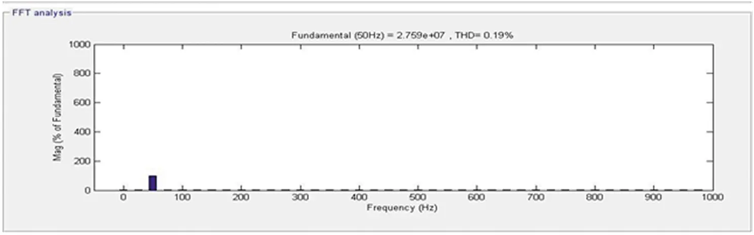
Figure 4.16 Source side frequency spectrum.
Читать дальшеИнтервал:
Закладка:
Похожие книги на «Active Electrical Distribution Network»
Представляем Вашему вниманию похожие книги на «Active Electrical Distribution Network» списком для выбора. Мы отобрали схожую по названию и смыслу литературу в надежде предоставить читателям больше вариантов отыскать новые, интересные, ещё непрочитанные произведения.


Обсуждение, отзывы о книге «Active Electrical Distribution Network» и просто собственные мнения читателей. Оставьте ваши комментарии, напишите, что Вы думаете о произведении, его смысле или главных героях. Укажите что конкретно понравилось, а что нет, и почему Вы так считаете.