Active Electrical Distribution Network
Здесь есть возможность читать онлайн «Active Electrical Distribution Network» — ознакомительный отрывок электронной книги совершенно бесплатно, а после прочтения отрывка купить полную версию. В некоторых случаях можно слушать аудио, скачать через торрент в формате fb2 и присутствует краткое содержание. Жанр: unrecognised, на английском языке. Описание произведения, (предисловие) а так же отзывы посетителей доступны на портале библиотеки ЛибКат.
- Название:Active Electrical Distribution Network
- Автор:
- Жанр:
- Год:неизвестен
- ISBN:нет данных
- Рейтинг книги:5 / 5. Голосов: 1
-
Избранное:Добавить в избранное
- Отзывы:
-
Ваша оценка:
Active Electrical Distribution Network: краткое содержание, описание и аннотация
Предлагаем к чтению аннотацию, описание, краткое содержание или предисловие (зависит от того, что написал сам автор книги «Active Electrical Distribution Network»). Если вы не нашли необходимую информацию о книге — напишите в комментариях, мы постараемся отыскать её.
Discover the major issues, solutions, techniques, and applications of active electrical distribution networks with this edited resource Active Electrical Distribution Network: A Smart Approach
Active Electrical Distribution Network: A Smart Approach
Active Electrical Distribution Network — читать онлайн ознакомительный отрывок
Ниже представлен текст книги, разбитый по страницам. Система сохранения места последней прочитанной страницы, позволяет с удобством читать онлайн бесплатно книгу «Active Electrical Distribution Network», без необходимости каждый раз заново искать на чём Вы остановились. Поставьте закладку, и сможете в любой момент перейти на страницу, на которой закончили чтение.
Интервал:
Закладка:
Apart from all the control algorithms, as mentioned above, indirect current control theory (ICCT) has the additional ability for fast regulation of the battery charging level and distributed system stability for transient conditions. Also, the proposed control algorithm provides a constant DC link voltage with fewer fluctuations.
This chapter aims to design an ICCT controlled DSTATCOM-BESS configuration for power conditioning in a distribution system with a balanced and unbalanced linear, nonlinear, and induction motor load. This detailed analysis helps beginners in selecting the type of load for the specific BESS-based configuration. The basic configuration of ICCT controlled DSTATCOM-BESS system is illustrated in Figure 4.1.
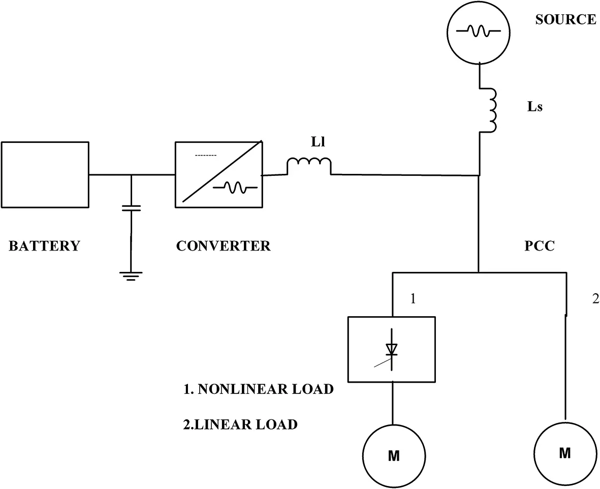
Figure 4.1 ICCT controlled DSTATCOM-BESS system connected at PCC.
4.2 System Configuration of D-STATCOM with BESS
The proposed ICCT-controlled DSTATCOM-BESS configuration is illustrated in Figure 4.2. This system is composed of various components such as a three-phase voltage source converter, energy storage device, ripple filter, and specific controller. The application of the proposed system is best suited for rural areas, where loads are unpredictable [23].
Three-phase VSC: The VSC is the core component of the D-STATCOM. During an abnormal condition, the VSC generates compensating current to support the voltage at the PCC under load unbalancing and provides reactive power compensation during a nonlinear load connection.
Energy storage: A Conventional STATCOM has only a DC-link capacitor for supporting the reactive power. However, the requirement for active and reactive power at a coupling point is frequent, while an unbalanced nonlinear load is connected. Hence, the DSTATCOM-BESS configuration is introduced for maintaining the DC-link voltage.
Filter: A small rating of the capacitive filter is introduced at the PCC for mitigating the ripples from the signals.
Controller: The proposed ICCT control algorithm estimates the gating signals for the accurate output voltage of the DSTATCOM-BESS. Also, the proposed algorithm has proved to be the best-suited control algorithm for power quality mitigation applications.
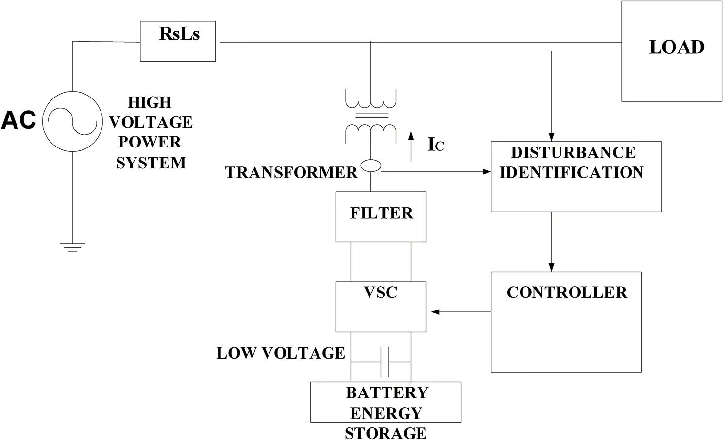
Figure 4.2 System scheme of D-STATCOM with BESS.
4.3 BESS Operation and Its Control
The proposed ICCT-controlled DSTATCOM-BESS system under current controlled operation is presented in Figure 4.3.
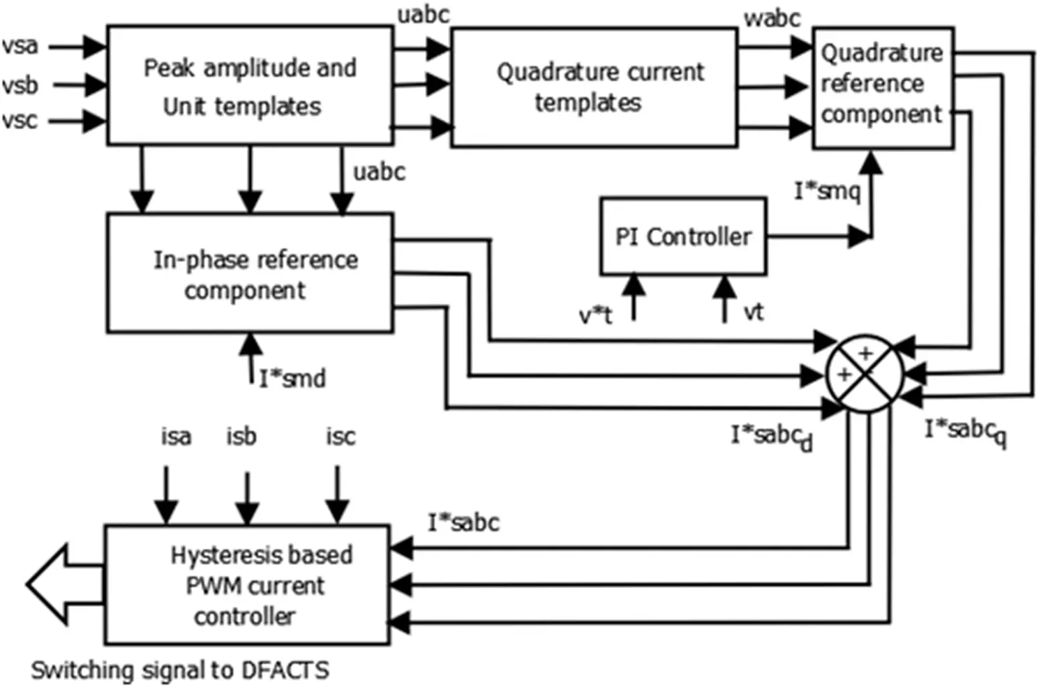
Figure 4.3 ICCT-based control algorithm for DSTATCOM-BESS.
The ICCT-based control algorithm consists of two components of three-phase reference currents with respect to phase-voltages, i.e. the in-phase component and the quadrature component. I * sad, I * sbdand I * scdare the in-phase components of the reference source currents. These are required for charging the battery of the BESS system which supports active power to the connected load. However, the other techniques for the generation of reference source currents for maintaining power quality are well discussed in [24].
The single point operation of load levelling can be illustrated by assigning a constant value of I * smd. However, the multiplication of the obtained value of in-phase voltage unit vectors ( Ua and Uc ) are calculated by dividing the AC voltages ( Va , Vb , and Vc ) using the peak amplitude ( Vm ), which provides the in-phase component of the reference currents ( I * sad, I * sbd, and I * scd). Also, estimation of the quadrature component of the source reference currents ( I * saq, I * sbq, and I * scq) is required for accurate control of the supply voltage at the PCC. Moreover, the quadrature unit vectors ( Wa , Wb , and Wc ) are perceived from the in-phase voltage unit vectors ( Ua , Ub , and Uc ). The peak amplitude of the voltage ( Vm ) is sensed at a coupling point and compared with the calculated reference voltage. This generates the voltage error. The obtained error is further passed through the proportional-integral voltage controller. The output of this controller ( I * smq) ensures that the AC voltage control and provides the amplitude of reactive current component required for the system. The multiplication of Wa , Wb , and Wc with I * smqhelps to estimate the quadrature component of the reference source signals ( I * saq, I * sbq, and I * scq). The addition of the quadrature component and in-phase component of the above-estimated reference signals provides the reference source currents ( I * sa, I * sb, and I * sc). However, the hysteresis-based current controller is implemented for the generation of gating pulses for the DSTATCOM-BESS system [25–27].
4.4 Discussion of the Simulation Results
The proposed system has been examined under balanced and unbalanced loading conditions for load levelling and balancing. Power quality disturbances are also mitigated using the proposed approach. The indirect current control (ICCT) theory is implemented to generate switching signals for the shunt connected DSTATCOM-based BESS, as illustrated in Figure 4.4.
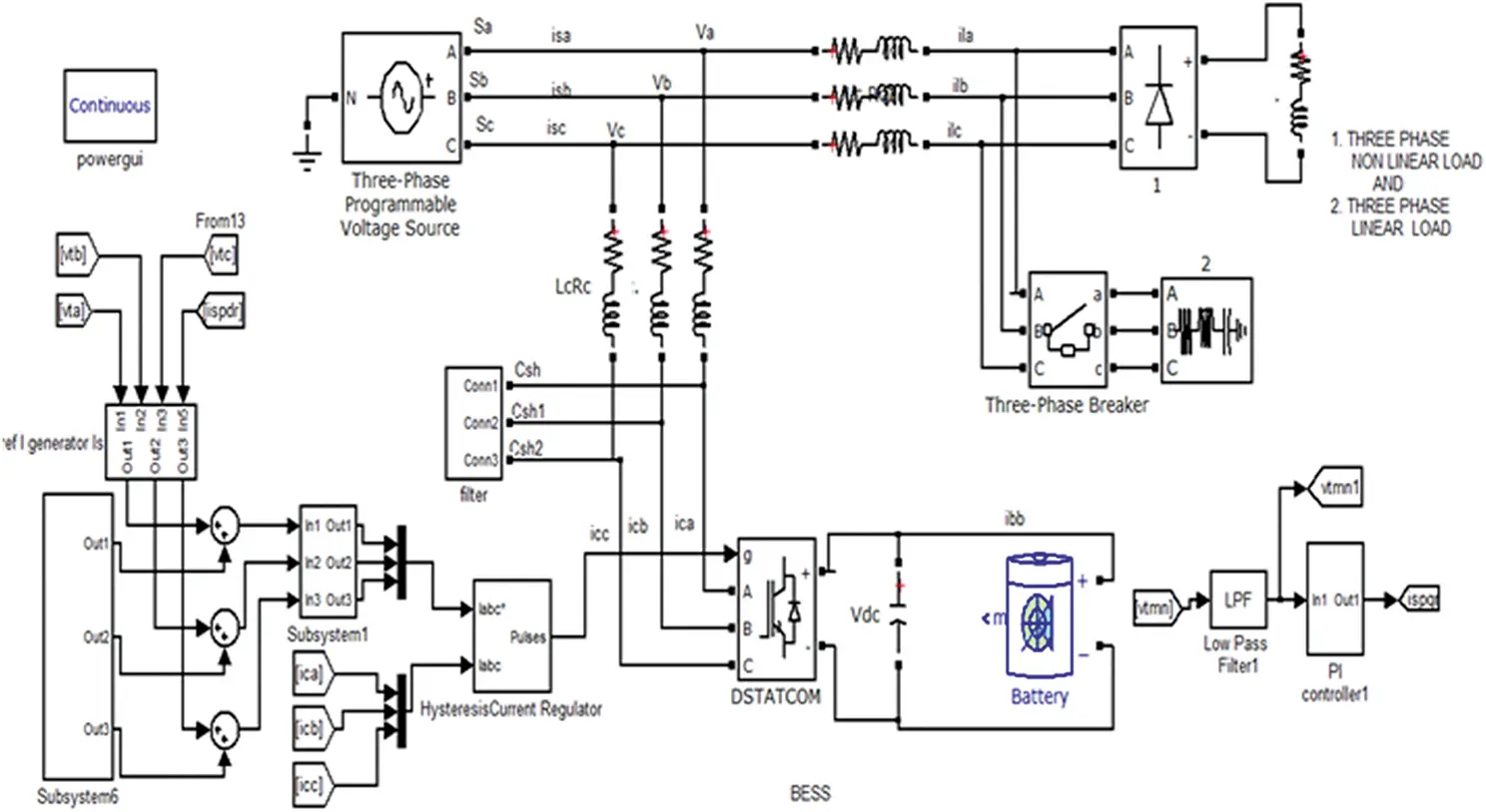
Figure 4.4 MATLAB simulation of indirect current control theory controlled for the DSTATCOM-BESS system.
4.5 Results Analysis under a Balanced System
The proposed system is analyzed under a balanced system condition that considers linear, nonlinear, and induction motor loads for demonstrating the performance on harmonic eliminations. The system is analyzed for source voltage ( Vs ), terminal voltage ( Vt ), source current ( Is ), compensating current ( Ic ), load currents ( Il ), battery voltage ( V b b ), and battery current ( I b b ) based signals. The parameters under the system consideration are as follows:
Source: Vpeak = 415 V, 3-Phase, 50 Hz
Linear load:Resistive load= 1000 Ω, Inductive load= 1e −3H
Nonlinear load:Rectifier-based inductive load with R load= 1000 Ω, L load= 1e −3H
Induction motor load:Nominal power = 3730VA, 415 V, 50 Hz and Tm = 10, hysteresis controller band 0.1
Battery and controller parameter: V OC= 720 V, R b1= 0.1 Ω, R b2= 1000 Ω, C b2= 1688 F, C dc= 5000 F, I * smd= 35
PI controller:Proportional constant = 043, Integrator constant = 0.15
4.5.1 Response of DSTATCOM-BESS under a Balanced Linear Load
The response of the DSTATCOM-BESS system with a balanced linear load is as depicted in Figure 4.5. The linear load varies from 1000 Ω to 1 Ω to test the battery charging operation. It has been perceived that the source voltage ( Vs ) and currents ( I sa) are balanced and in-phase under the battery charging condition ( I b b ). Load currents ( I l) are observed to be balanced when keeping the balanced terminal at its reference voltage. Also during the operation the compensating current ( Ic ) is in balance and continuously provides the required current.
Читать дальшеИнтервал:
Закладка:
Похожие книги на «Active Electrical Distribution Network»
Представляем Вашему вниманию похожие книги на «Active Electrical Distribution Network» списком для выбора. Мы отобрали схожую по названию и смыслу литературу в надежде предоставить читателям больше вариантов отыскать новые, интересные, ещё непрочитанные произведения.


Обсуждение, отзывы о книге «Active Electrical Distribution Network» и просто собственные мнения читателей. Оставьте ваши комментарии, напишите, что Вы думаете о произведении, его смысле или главных героях. Укажите что конкретно понравилось, а что нет, и почему Вы так считаете.