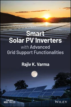
Rajiv K. Varma - Smart Solar PV Inverters with Advanced Grid Support Functionalities
Здесь есть возможность читать онлайн «Rajiv K. Varma - Smart Solar PV Inverters with Advanced Grid Support Functionalities» — ознакомительный отрывок электронной книги совершенно бесплатно, а после прочтения отрывка купить полную версию. В некоторых случаях можно слушать аудио, скачать через торрент в формате fb2 и присутствует краткое содержание. Жанр: unrecognised, на английском языке. Описание произведения, (предисловие) а так же отзывы посетителей доступны на портале библиотеки ЛибКат.
- Название:Smart Solar PV Inverters with Advanced Grid Support Functionalities
- Автор:
- Жанр:
- Год:неизвестен
- ISBN:нет данных
- Рейтинг книги:3 / 5. Голосов: 1
-
Избранное:Добавить в избранное
- Отзывы:
-
Ваша оценка:
- 60
- 1
- 2
- 3
- 4
- 5
Smart Solar PV Inverters with Advanced Grid Support Functionalities: краткое содержание, описание и аннотация
Предлагаем к чтению аннотацию, описание, краткое содержание или предисловие (зависит от того, что написал сам автор книги «Smart Solar PV Inverters with Advanced Grid Support Functionalities»). Если вы не нашли необходимую информацию о книге — напишите в комментариях, мы постараемся отыскать её.
Smart Solar PV Inverters with Advanced Grid Support Functionalities
Smart Solar PV Inverters with Advanced Grid Support Functionalities’
Smart Solar PV Inverters with Advanced Grid Support Functionalities — читать онлайн ознакомительный отрывок
Ниже представлен текст книги, разбитый по страницам. Система сохранения места последней прочитанной страницы, позволяет с удобством читать онлайн бесплатно книгу «Smart Solar PV Inverters with Advanced Grid Support Functionalities», без необходимости каждый раз заново искать на чём Вы остановились. Поставьте закладку, и сможете в любой момент перейти на страницу, на которой закончили чтение.
Интервал:
Закладка:
6 Chapter 6Figure 6.1 Single line diagram of (a) study system I with single solar farm ...Figure 6.2 Overall DG (solar/wind) system model with damping controller and ...Figure 6.3 (a) Maximum nighttime power transfer (850 MW) from generator with...Figure 6.4 (a) Maximum nighttime power transfer (899 MW) from generator with...Figure 6.5 Maximum daytime power transfer (719 MW) from generator with solar...Figure 6.6 Maximum daytime power transfer (861 MW) from generator with solar...Figure 6.7 Maximum nighttime power transfer from generator with both DGs usi...Figure 6.8 Maximum daytime power transfer from generator while both DGs gene...Figure 6.9 Single‐line diagram of two‐area system with 100 MW PV plant conne...Figure 6.10 PV‐STATCOM controller.Figure 6.11 Flowchart of the operation of oscillation detection unit.Figure 6.12 Residue analysis for PV‐STATCOM POD controller.Figure 6.13 Midline and PV active power in two‐area system (230 and 430 MW p...Figure 6.14 (a) Midline and PV active power, (b) PV reactive power, (c) midl...Figure 6.15 (a) Midline and PV active power, (b) PV reactive power, (c) Midl...Figure 6.16 Nighttime (a) Midline active power without POD with PV‐STATCOM c...Figure 6.17 Effect of PV‐STATCOM control on system frequency in two‐area pow...Figure 6.18 Single‐line diagram of two‐area power system with PV‐STATCOM con...Figure 6.19 Detailed nonlinear and small‐signal model of PV‐STATCOM control....Figure 6.20 Flowchart of PV‐STATCOM operation mode selection.Figure 6.21 Residue analysis for PV‐STATCOM Q‐POD controller.Figure 6.22 Residue analysis for PV‐STATCOM P‐POD controller.Figure 6.23 Maximum power transfer capability of the two‐area power system....Figure 6.24 Midline active power; and PV‐STATCOM active power, reactive powe...Figure 6.25 Power system frequency for No POD, Q‐POD, P‐POD, and PQ‐POD cont...Figure 6.26 Study system involving a PV solar farm connected at the synchron...Figure 6.27 Damping controller configuration.Figure 6.28 (a) DC voltage controller, (b) flowchart of DC voltage controlle...Figure 6.29 System response for Mode 1 SSR without PV‐STATCOM controller....Figure 6.30 PV‐STATCOM response for damping of Critical Mode 1 SSR.Figure 6.31 Synchronous generator response for damping of Critical Mode 1 SS...Figure 6.32 Transmission system response for damping of Critical Mode 1 SSR....Figure 6.33 System response for Mode 1 SSR without damping controller during...Figure 6.34 System response for damping of Critical Mode 4 SSR.Figure 6.35 Study system: (a) modified IEEE First SSR Benchmark System with ...Figure 6.36 Windfarm response, without and with PV‐STATCOM controller, P WF=...Figure 6.37 System response with PV‐STATCOM controller, P WF= 500 MW, PV sys...Figure 6.38 System response without and with PV‐STATCOM controller, P WF= 50...Figure 6.39 System response without and with PV‐STATCOM controller, nighttim...Figure 6.40 Single line diagram of the study system.Figure 6.41 Single line diagram of a large PV plant with the proposed PV‐STA...Figure 6.42 (a) Typical active “P” and reactive power “Q” exchange capabilit...Figure 6.43 Response of IMs with PV plant without any control. (a) PCC volta...Figure 6.44 Response of the large PV plant with proposed PV‐STATCOM control....Figure 6.45 Comparison of PV‐STATCOM and other smart inverter controls. (a) ...Figure 6.46 Performance comparison of PV‐STATCOM and actual STATCOM. (a) PCC...Figure 6.47 Impact on system frequency.Figure 6.48 Performance of PV‐STATCOM at night. (a) PCC voltage (RMS), (b) 2...Figure 6.49 Two‐area four‐machine study system.Figure 6.50 Modified WECC generic dynamic model of PV power plant.Figure 6.51 Simultaneous FFR and POD control scheme in a PV‐STATCOM plant co...Figure 6.52 Simultaneous modulation of active power and reactive power with ...Figure 6.53 25 MW load rejection in area 1 ( P available= 100 MW, K curt= 0):...Figure 6.54 200 MW load rejection in area 1 ( P available= 60 MW, K curt= 0):...Figure 6.55 25 MW load increase in area 1 ( P available= 100 MW, K curt= 50%)...Figure 6.56 100 MW load increase in area 1 ( P available= 100 MW, K curt= 50%...Figure 6.57 100 MW load increase in area 2, PV plant output curtailed by 50%...
7 Chapter 7Figure 7.1 Hosting capacity of a distribution feeder. (a) PV systems operati...Figure 7.2 Additional energy storage needed to achieve a marginal PV net LCO...Figure 7.3 Study system.Figure 7.4 Additional PV hosting capacity using APC.Figure 7.5 Additional PV hosting capacity using different module orientation...Figure 7.6 PV hosting capacity of the 10 node test feeder in accordance with...Figure 7.7 Additional PV hosting capacity using DSM.Figure 7.8 Additional PV hosting capacity using distributed storage systems....Figure 7.9 PV hosting capacity (absolute and additional) using RPC.Figure 7.10 Voltage comparison with different PV inverter controls.Figure 7.11 Key characteristics of 17 test feeders: voltage class, maximum l...Figure 7.12 PV hosting capacity results of 17 test feeders.Figure 7.13 Correlation between PV hosting capacity and feeder characteristi...Figure 7.14 Volt‐var function; V 1= 0.95 pu, Q 1= 100%, V 2= 1.05 pu, Q 2= 1...Figure 7.15 PV hosting capacity results of 17 test feeders after applying va...Figure 7.16 Voltage responses obtained with different volt–var settings.Figure 7.17 Methodology for determining optimal smart inverter controller pa...Figure 7.18 Volt–var control curves with deadband.Figure 7.19 Consideration of voltage constraint during optimization of perfo...Figure 7.20 Study distribution system.Figure 7.21 Aggregate solar and customer load profile over a day.Figure 7.22 Voltage profile over the day for the three study cases.Figure 7.23 Combined volt–var and volt–watt smart inverter functions.Figure 7.24 Volt–var control curves: (a) with deadband and (b) without deadb...Figure 7.25 Feeder voltage profile as a function of distance for 1 March 201...Figure 7.26 Normalized power losses with respect to feeder without SI in fee...Figure 7.27 Case study feeder with the location of new PV (triangle) and tec...Figure 7.28 Visual representation of international default settings of volt–...Figure 7.29 Visual representation of international settings of volt–var func...Figure 7.30 Analysis of volt–watt settings (a) voltage and (b) active power....Figure 7.31 Analysis of volt–var settings (a) voltage, (b) reactive power, a...Figure 7.32 Analysis of watt–PF settings (a) voltage, (b) reactive power, an...Figure 7.33 Analysis of fixed power factor settings.Figure 7.34 Baseline hosting capacity analysis process applied separately fo...Figure 7.35 Comparison of watt and var priority for a specific setting on a ...Figure 7.36 Volt–var with var priority curves that achieved a 25% increase i...Figure 7.37 Distribution circuit of Porterville, CA [47].Figure 7.38 PV system POI voltage and reactive power exchange on 23 November...Figure 7.39 Start of the circuit current magnitude in Phase A and reactive p...Figure 7.40 Daily behavior of smart PV inverter with Q ( V ) and P ( V ) functio...Figure 7.41 Demonstration of volt–var control on a 1.1 MW PV system on a sun...Figure 7.42 Demonstration of volt–var control on a 1.1 MW PV system on a clo...
8 Chapter 8Figure 8.1 MV grid based on the CIGRE MV benchmark grid. (a) results of the ...Figure 8.2 Voltage variations d V caused by all PV systems. (a) at node T1, (...Figure 8.3 Study feeder system.Figure 8.4 Different volt–var curves considered for smart PV inverters.Figure 8.5 LTC tap operations during a clear day (left) and variable day (ri...Figure 8.6 Control scheme of power factor and output power of smart inverter...Figure 8.7 Profiles of active power generation and bus voltage of test PV fa...Figure 8.8 Profiles of active power generation, reactive power compensation,...Figure 8.9 SVC interaction analysis network.Figure 8.10 A proposed Hydro‐Quebec summertime study system with shunt compe...Figure 8.11 SVC transient behavior in La Verendrye system due to “snapshot” ...Figure 8.12 The effect of the SVC response rate on system eigenvalues in La ...Figure 8.13 (a) Simplified grid‐connected model of the smart PV inverter, (b...Figure 8.14 Single smart inverter connected to a simple network.Figure 8.15 Distribution line with two smart PV inverters.Figure 8.16 Normal operation of two PV inverters with volt–var control. (a) ...Figure 8.17 Control interaction between two smart inverters with different v...Figure 8.18 Voltage control through volt–var function.Figure 8.19 (a) Volt–var function for base case, (b) volt–var function for c...Figure 8.20 Voltage response of both inverters with K P= 0.3 and K I= 3.0, v...Figure 8.21 Voltage response of both inverters with slope of volt–var curve ...Figure 8.22 Different volt–var characteristics implemented on PV systems....Figure 8.23 Bus voltage and reactive power output of a PV system, without va...Figure 8.24 Bus voltage and reactive power output of the PV system, with var...Figure 8.25 Study system for smart PV inverter controller interactions.Figure 8.26 Control system of the smart PV inverters.Figure 8.27 DER inverter connected to infinite bus.Figure 8.28 Volt–var function (a) and volt–watt function (b) operative in th...Figure 8.29 Time‐domain response of voltage E kat the point of connection of...Figure 8.30 Single line diagram of study system.Figure 8.31 Block diagram of the volt–var control in the PV plant connected ...Figure 8.32 Typical volt–var curve of a smart inverter.Figure 8.33 Structure of a volt–var controller.Figure 8.34 Variation of dominant poles in ( σ + jω ) plane, for var...Figure 8.35 Variation of dominant poles in ( σ + jω ) plane, for var...Figure 8.36 Reactive power output ( Q ) of both PV plants for delays of: (a) 0...Figure 8.37 Reactive power output ( Q ) of both PV plants for response time of...Figure 8.38 Study system: DFIG‐based wind farm and solar PV farm connected t...Figure 8.39 Subsynchronous damping controller (SSDC) of DFIG converter.Figure 8.40 Control system of PV‐STATCOM.Figure 8.41 System response without subsynchronous damping controllers. (a) ...Figure 8.42 Performance of uncoordinated SSDCs of PV‐STATCOM and DFIG: (a) l...Figure 8.43 DFIG and PV system responses with coordinated SSDCs of PV‐STATCO...Figure 8.44 Performance of coordinated SSDCs of PV‐STATCOM and DFIG: (a) lin...
Читать дальшеИнтервал:
Закладка:
Похожие книги на «Smart Solar PV Inverters with Advanced Grid Support Functionalities»
Представляем Вашему вниманию похожие книги на «Smart Solar PV Inverters with Advanced Grid Support Functionalities» списком для выбора. Мы отобрали схожую по названию и смыслу литературу в надежде предоставить читателям больше вариантов отыскать новые, интересные, ещё непрочитанные произведения.
Обсуждение, отзывы о книге «Smart Solar PV Inverters with Advanced Grid Support Functionalities» и просто собственные мнения читателей. Оставьте ваши комментарии, напишите, что Вы думаете о произведении, его смысле или главных героях. Укажите что конкретно понравилось, а что нет, и почему Вы так считаете.


