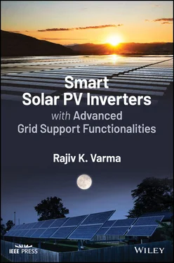
Rajiv K. Varma - Smart Solar PV Inverters with Advanced Grid Support Functionalities
Здесь есть возможность читать онлайн «Rajiv K. Varma - Smart Solar PV Inverters with Advanced Grid Support Functionalities» — ознакомительный отрывок электронной книги совершенно бесплатно, а после прочтения отрывка купить полную версию. В некоторых случаях можно слушать аудио, скачать через торрент в формате fb2 и присутствует краткое содержание. Жанр: unrecognised, на английском языке. Описание произведения, (предисловие) а так же отзывы посетителей доступны на портале библиотеки ЛибКат.
- Название:Smart Solar PV Inverters with Advanced Grid Support Functionalities
- Автор:
- Жанр:
- Год:неизвестен
- ISBN:нет данных
- Рейтинг книги:3 / 5. Голосов: 1
-
Избранное:Добавить в избранное
- Отзывы:
-
Ваша оценка:
- 60
- 1
- 2
- 3
- 4
- 5
Smart Solar PV Inverters with Advanced Grid Support Functionalities: краткое содержание, описание и аннотация
Предлагаем к чтению аннотацию, описание, краткое содержание или предисловие (зависит от того, что написал сам автор книги «Smart Solar PV Inverters with Advanced Grid Support Functionalities»). Если вы не нашли необходимую информацию о книге — напишите в комментариях, мы постараемся отыскать её.
Smart Solar PV Inverters with Advanced Grid Support Functionalities
Smart Solar PV Inverters with Advanced Grid Support Functionalities’
Smart Solar PV Inverters with Advanced Grid Support Functionalities — читать онлайн ознакомительный отрывок
Ниже представлен текст книги, разбитый по страницам. Система сохранения места последней прочитанной страницы, позволяет с удобством читать онлайн бесплатно книгу «Smart Solar PV Inverters with Advanced Grid Support Functionalities», без необходимости каждый раз заново искать на чём Вы остановились. Поставьте закладку, и сможете в любой момент перейти на страницу, на которой закончили чтение.
Интервал:
Закладка:
2 Chapter 2 Figure 2.1 P–Q capability curve of a distributed energy resource. Figure 2.2 Reactive power capability of a typical synchronous generator comp... Figure 2.3 Depiction of different interconnecting buses. Figure 2.4 Minimum reactive power capability of Category B DERs. Figure 2.5 Constant power factor function. Figure 2.6 Volt–var curve of a DER. Figure 2.7 Default volt–var settings for different international standards.... Figure 2.8 Typical watt–var characteristic. Figure 2.9 Dynamic reactive current injection. Figure 2.10 Dynamic reactive current support function. Figure 2.11 Volt–watt characteristic for DER (a) without energy storage; (b)... Figure 2.12 International default volt–watt settings normalized to ANSI volt... Figure 2.13 Combined operation of volt–var mode and volt–watt mode of operat... Figure 2.14 Dynamic volt–watt function. Figure 2.15 DER response to abnormal voltages and voltage ride‐through requi... Figure 2.16 DER response to abnormal voltages and voltage ride‐through requi... Figure 2.17 Voltage ride‐through time duration curve from NERC. *The area ou... Figure 2.18 Frequency watt function 1. Figure 2.19 Frequency watt function 2. Figure 2.20 Frequency‐droop function curves. Figure 2.21 Frequency watt function with battery energy storage. Figure 2.22 DER default response to abnormal frequencies and frequency ride‐... Figure 2.23 Off nominal frequency capability curve from NERC (a) Eastern int... Figure 2.24 Charging function of the ESS‐based DER. Figure 2.25 State of charge (SOC)‐based model of ESS.
3 Chapter 3Figure 3.1 A smart inverter system connected to the power system.Figure 3.2 Active and reactive power flow from the smart inverter system tow...Figure 3.3 Reactive power injection by the smart inverter system.Figure 3.4 Reactive power absorption by the smart inverter system.Figure 3.5 Control system of a smart PV inverter system.Figure 3.6 Typical I–V characteristic of a PV module at (a) different ...Figure 3.7 Variation of power output from a PV solar panel.Figure 3.8 A two‐level Voltage Source Converter.Figure 3.9 AC filter.Figure 3.10 Phasor diagram of space phasor  in abc and dq reference frames....Figure 3.11 Sinusoidal pulse width modulation. (a) Modulating signal and car...Figure 3.12 Phasor diagram prior to synchronization by PLL.Figure 3.13 Phasor diagram after synchronization by PLL.Figure 3.14 Block diagram of a Phase Locked Loop.Figure 3.15 Block diagram of the current controller.Figure 3.16 Block diagram of DC‐link voltage controller.Figure 3.17 Implementation of volt–var smart inverter function.Figure 3.18 Block diagram of PCC voltage controller.Figure 3.19 Typical topology of a solar PV plant.
4 Chapter 4Figure 4.1 Single machine connected to infinite bus.Figure 4.2 Comparison of different power flow limits in a transmission line....Figure 4.3 A TSC–TCR based SVC.Figure 4.4 Typical control system of SVC.Figure 4.5 Synchronous condenser.Figure 4.6 Variation of synchronous condenser armature current with change i...Figure 4.7 STATCOM with DC capacitor (no energy storage). (a) power circuit,...Figure 4.8 Typical Voltage versus Current characteristics of a) STATCOM and ...Figure 4.9 Typical control system of a STATCOM.Figure 4.10 (a) Typical low voltage ride‐through characteristic; (b) typical...Figure 4.11 Voltage profile across a long transmission line.Figure 4.12 Voltage profile across a long transmission line with dynamic rea...Figure 4.13 Single machine infinite bus (SMIB) system with a mid‐line connec...Figure 4.14 (a) A basic PV solar system, (b) A basic STATCOM, and (c) A basi...Figure 4.15 PV‐STATCOM capability of PV inverter in active power priority mo...Figure 4.16 PV‐STATCOM operation in reactive power priority mode. Active pow...Figure 4.17 PV‐STATCOM operation in reactive power priority mode: Active pow...Figure 4.18 Combined modulation of active and reactive power after partial c...Figure 4.19 Simultaneous modulation of active power and reactive power with ...
5 Chapter 5Figure 5.1 Single‐line diagram of the distributed generation study system....Figure 5.2 Solar farm as STATCOM – controller diagram. (a) synchronization, ...Figure 5.3 Solar farm as STATCOM – PCC voltage regulation. (a) PCC voltage p...Figure 5.4 Solar farm as STATCOM – transient performance during 3LG fault. (...Figure 5.5 Single‐line diagram of a realistic feeder in Ontario.Figure 5.6 PV‐STATCOM control system.Figure 5.7 Variation in PCC voltage with increasing wind power during nightt...Figure 5.8 Variation in PCC voltage with increasing wind power during daytim...Figure 5.9 Transient overvoltage at load end during nighttime condition (a) ...Figure 5.10 Relation between distance of wind farm from PV‐STATCOM and react...Figure 5.11 Overall increase in wind farm penetration.Figure 5.12 Modeling of the study system and PV‐STATCOM controller component...Figure 5.13 Flowchart of the PV‐STATCOM operating modes.Figure 5.14 Simulation results for Full STATCOM mode with voltage control du...Figure 5.15 Simulation results for Full STATCOM mode with voltage control du...Figure 5.16 Simulation results for LVRT test with smart PV system during day...Figure 5.17 Single‐line diagram of the study system.Figure 5.18 Modeling of the study system and control components.Figure 5.19 Flowchart of the smart PV inverter PV‐STATCOM operating modes....Figure 5.20 Structure of TOV detection block.Figure 5.21 Performance of three conventional PV systems during small load a...Figure 5.22 Performance of the third 10 MW PV system as PV‐STATCOM, together...Figure 5.23 Performance of one PV system with proposed smart inverter contro...Figure 5.24 PV‐STATCOM control for line loss minimization (a) optimal power ...Figure 5.25 One line diagram of (a) Scenario 1 and (b) Scenario 2.Figure 5.26 PV power generation profile and available reactive power capacit...Figure 5.27 Modified one line diagram of IEEE 33 Bus system with PV solar fa...Figure 5.28 Load profile for typical day as created from IESO data.Figure 5.29 (a) Active power loss without PV systems, with PV systems and wi...Figure 5.30 Voltage profile without PV system, with conventional PV system o...Figure 5.31 Single‐line diagram of the Study System 1.Figure 5.32 A PV system connected to Study System 2 with the proposed PV‐STA...Figure 5.33 (a) Active power output ( P ) and reactive power capability ( Q ) of...Figure 5.34 Response of induction motor with and without PV‐STATCOM control....Figure 5.35 Performance comparison of remotely located PV‐STATCOM and locall...Figure 5.36 PV solar system operating at unity power factor (without PV‐STAT...Figure 5.37 Response of PV operating according to German grid code. (a) Moto...Figure 5.38 Motor stabilization by PV‐STATCOM operation at night. (a) Motor ...
Читать дальшеИнтервал:
Закладка:
Похожие книги на «Smart Solar PV Inverters with Advanced Grid Support Functionalities»
Представляем Вашему вниманию похожие книги на «Smart Solar PV Inverters with Advanced Grid Support Functionalities» списком для выбора. Мы отобрали схожую по названию и смыслу литературу в надежде предоставить читателям больше вариантов отыскать новые, интересные, ещё непрочитанные произведения.
Обсуждение, отзывы о книге «Smart Solar PV Inverters with Advanced Grid Support Functionalities» и просто собственные мнения читателей. Оставьте ваши комментарии, напишите, что Вы думаете о произведении, его смысле или главных героях. Укажите что конкретно понравилось, а что нет, и почему Вы так считаете.


