Distributed Acoustic Sensing in Geophysics
Здесь есть возможность читать онлайн «Distributed Acoustic Sensing in Geophysics» — ознакомительный отрывок электронной книги совершенно бесплатно, а после прочтения отрывка купить полную версию. В некоторых случаях можно слушать аудио, скачать через торрент в формате fb2 и присутствует краткое содержание. Жанр: unrecognised, на английском языке. Описание произведения, (предисловие) а так же отзывы посетителей доступны на портале библиотеки ЛибКат.
- Название:Distributed Acoustic Sensing in Geophysics
- Автор:
- Жанр:
- Год:неизвестен
- ISBN:нет данных
- Рейтинг книги:5 / 5. Голосов: 1
-
Избранное:Добавить в избранное
- Отзывы:
-
Ваша оценка:
Distributed Acoustic Sensing in Geophysics: краткое содержание, описание и аннотация
Предлагаем к чтению аннотацию, описание, краткое содержание или предисловие (зависит от того, что написал сам автор книги «Distributed Acoustic Sensing in Geophysics»). Если вы не нашли необходимую информацию о книге — напишите в комментариях, мы постараемся отыскать её.
Distributed Acoustic Sensing in Geophysics Methods and Applications Distributed Acoustic Sensing (DAS) is a technology that records sound and vibration signals along a fiber optic cable. Its advantages of high resolution, continuous, and real-time measurements mean that DAS systems have been rapidly adopted for a range of applications, including hazard mitigation, energy industries, geohydrology, environmental monitoring, and civil engineering.
presents experiences from both industry and academia on using DAS in a range of geophysical applications. Volume highlights include: The American Geophysical Union promotes discovery in Earth and space science for the benefit of humanity. Its publications disseminate scientific knowledge and provide resources for researchers, students, and professionals.
Distributed Acoustic Sensing in Geophysics — читать онлайн ознакомительный отрывок
Ниже представлен текст книги, разбитый по страницам. Система сохранения места последней прочитанной страницы, позволяет с удобством читать онлайн бесплатно книгу «Distributed Acoustic Sensing in Geophysics», без необходимости каждый раз заново искать на чём Вы остановились. Поставьте закладку, и сможете в любой момент перейти на страницу, на которой закончили чтение.
Интервал:
Закладка:
Here, we present a real‐time PGC‐DAS system. Combined with characteristics of large dynamic range and high sensitivity of PGC demodulation algorithm (Wang et al., 2015), the proposed system provides an effective technical solution to distributed fiber acoustic sensing. The sensing distance could reach 10 km with the minimum sample interval of 0.4 m. Corresponding to the average phase noise of 5 × 10 ‐4rad/√Hz, a strain sensitivity of 8.5 pε/√Hz was achieved with a spatial resolution of 10 m, as well as a frequency response range of 2 Hz to 1 kHz over 10 km sensing distance. A field trial of this PGC‐DAS system was performed to compare nodal geophones. Results show that seismic records have a high consistency between them, proving the feasibility of PGC‐DAS system in seismology.
4.2. PRINCIPLE
The principle of PGC‐DAS system is shown in Figure 4.1. A coherent input light pulse passes through a circulator into the sensing optical fiber. RB light enters into an unbalanced MI with FRMs at the ends. There is a phase modulator on one arm of MI and an optical delay L MIon the other arm. RB signal mixes with itself and is detected by one photoelectric detector (PD).
Intensity distribution of RB light is a type of Fourier transform of random permittivity fluctuations (Bao et al., 2016). Assume that the sensing fiber is composed of successive slices with a length of Δ L . Each slice contains M scattering centers, and polarization states between each scattering center are consistent. The interference field of backscattered light at distance L m= m Δ L can be expressed by (Park et al., 1998):
(4.1) 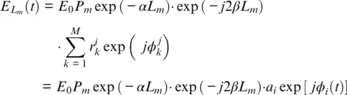
where E 0is electric field intensity of the incident light; P mis polarization‐dependent coefficient ranging from 0 to 1; α is optical power attenuation coefficient; r kand φ kare scattering coefficient and phase of the k th scattering center, respectively; a iand φ iare reflectivity and phase of scattering unit, respectively; and β is propagation constant.
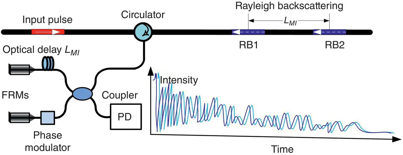
Figure 4.1 Principle of PGC‐DAS system with an unbalanced MI.
Then, scattering light enters into MI, and RB1 and RB2 separated by L MIinterference due to the same optical path. The interference electrical field E ( t ) is written as:
(4.2) 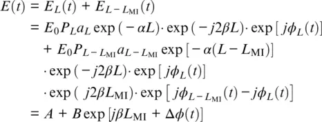
With simplified coefficients A and B , the interference intensity is given by:
(4.3) 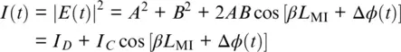
For PGC demodulation algorithm, a sinusoidal signal with a modulation frequency of ω cis loaded on one arm of MI. Therefore, an additional phase modulation C ⋅ cos ( ω c t ) is introduced in Equation 4.3with C = m Δ L MI, where m is the modulation index and Δ L MIis the maximum length difference variation. Hence, the total phase of the interference light is:
(4.4) 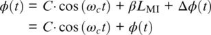
And the interference intensity is rewritten as:
(4.5) 
After being multiplied separately with fundamental and second harmonic carriers cos( ω c t ) andcos(2 ω c t ), and later with low‐pass filtering, the in‐phase and quadrature components I I( t ) and I Q( t ) are represented as (Dandridge et al., 1982):
(4.6) 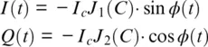
where J 1( C ) and J 2( C ) are the first‐order and the second‐order Bessel function, respectively, of the first kind. When C is equal to 2.63, it satisfies J 1( C ) = J 2( C ). Thus, the phase φ ( t ) is calculated by:
(4.7) 
4.3. EXPERIMENTS AND RESULTS
The PGC‐DAS system setup is illustrated in Figure 4.2. A 1550.15 nm coherent laser with a bandwidth of 3 kHz is modulated by AOM with an extinction ratio of 50 dB to an optical pulse. The pulse width and repetition rate are 50 ns and 8 kHz, respectively. The pulse light travels through an optical isolator (ISO) and is amplified by an erbium‐doped fiber amplifier (EDFA). A fiber Bragg grating is utilized to filter redundancy in amplified spontaneous emission (ASE). The filtered pulse light is launched into the sensing fiber through a circulator. After that, RB light is injected into an unbalanced MI with a one‐way optical path difference of 10 m, i.e., L MI= 10 m. FRMs are used to eliminate the influence of polarization fading. The mixed interference RB light is modulated by a sinusoidal signal with a modulation amplitude of 2.63 rad and arrives at the high‐sensitivity optical detector (PD) with a bandwidth of 80 MHz. After analog‐to‐digital conversion at the analog digital converter (ADC), the obtained RB signal is sampled with a sampling rate of 250 MS/s, corresponding to the minimum sampling interval of 0.4 m. PGC demodulation scheme is implemented on a digital processing unit consisting of field programmable gate array/digital signal processor (FPGA/DSP) circuits and a real‐time controller, which could realize more than 10,000 channels’ real‐time phase calculation. The sensing fiber is a 10 km standard single‐mode fiber, and a fiber stretcher with a 6 m single‐mode fiber wound on a piezoelectric ceramic tube is inserted in the sensing fiber as a unit under test. An isolator is placed at the end of the sensing fiber to remove unwanted end reflection.
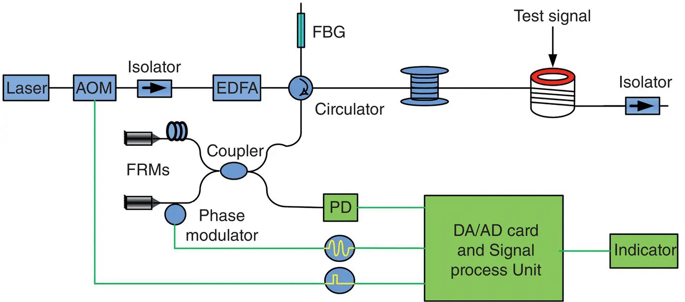
Figure 4.2 Setup of PGC‐DAS system.
The time series in Figure 4.3a contains 9,995 data points of Channel #4750. These data points are sampled with a time increment of 0.5 ms, which conceivably allows the time series to contain frequency content up to a Nyquist frequency of 1 kHz ( Figure 4.3b). To remove quasi‐static phase drift caused by environmental effects, a high‐pass filter with a cutoff frequency of 2 Hz is adopted in the procedure. Thus, the frequency response range is limited to 2 Hz to 1 kHz.
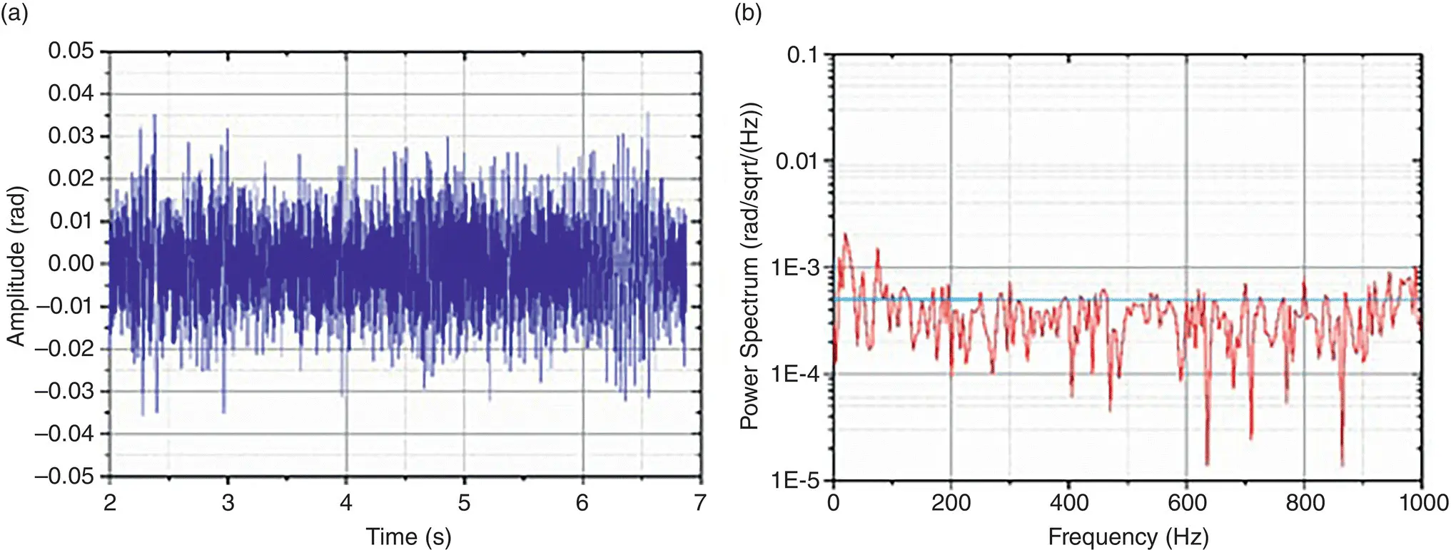
Figure 4.3 Phase noise of PGC‐DAS system on Channel #4750: (a) Time series and (b) power spectrum.
Читать дальшеИнтервал:
Закладка:
Похожие книги на «Distributed Acoustic Sensing in Geophysics»
Представляем Вашему вниманию похожие книги на «Distributed Acoustic Sensing in Geophysics» списком для выбора. Мы отобрали схожую по названию и смыслу литературу в надежде предоставить читателям больше вариантов отыскать новые, интересные, ещё непрочитанные произведения.


Обсуждение, отзывы о книге «Distributed Acoustic Sensing in Geophysics» и просто собственные мнения читателей. Оставьте ваши комментарии, напишите, что Вы думаете о произведении, его смысле или главных героях. Укажите что конкретно понравилось, а что нет, и почему Вы так считаете.