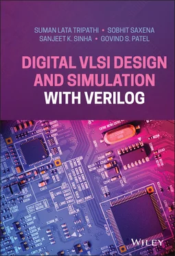
Suman Lata Tripathi - Digital VLSI Design and Simulation with Verilog
Здесь есть возможность читать онлайн «Suman Lata Tripathi - Digital VLSI Design and Simulation with Verilog» — ознакомительный отрывок электронной книги совершенно бесплатно, а после прочтения отрывка купить полную версию. В некоторых случаях можно слушать аудио, скачать через торрент в формате fb2 и присутствует краткое содержание. Жанр: unrecognised, на английском языке. Описание произведения, (предисловие) а так же отзывы посетителей доступны на портале библиотеки ЛибКат.
- Название:Digital VLSI Design and Simulation with Verilog
- Автор:
- Жанр:
- Год:неизвестен
- ISBN:нет данных
- Рейтинг книги:3 / 5. Голосов: 1
-
Избранное:Добавить в избранное
- Отзывы:
-
Ваша оценка:
- 60
- 1
- 2
- 3
- 4
- 5
Digital VLSI Design and Simulation with Verilog: краткое содержание, описание и аннотация
Предлагаем к чтению аннотацию, описание, краткое содержание или предисловие (зависит от того, что написал сам автор книги «Digital VLSI Design and Simulation with Verilog»). Если вы не нашли необходимую информацию о книге — напишите в комментариях, мы постараемся отыскать её.
Digital VLSI Design Problems and Solution with Verilog
Digital VLSI Design Problems and Solution with Verilog
Digital VLSI Design and Simulation with Verilog — читать онлайн ознакомительный отрывок
Ниже представлен текст книги, разбитый по страницам. Система сохранения места последней прочитанной страницы, позволяет с удобством читать онлайн бесплатно книгу «Digital VLSI Design and Simulation with Verilog», без необходимости каждый раз заново искать на чём Вы остановились. Поставьте закладку, и сможете в любой момент перейти на страницу, на которой закончили чтение.
Интервал:
Закладка:
9 Chapter 9Figure 9.1 VLSI design flow at RTL level.Figure 9.2 Example of function implementation with PROM.Figure 9.3 Example of function implementation with PAL.Figure 9.4 Example of function implementation PLA.Figure 9.5 CPLD block diagram.Figure 9.6 PAL-macrocellFigure 9.7 FPGA block diagram.Figure 9.8 2-Input LUT.Figure 9.9 3-Input LUT.Figure 9.10 Digital design flow.
10 Chapter 10Figure 10.1 New project creation on Xilinx ISE simulator.Figure 10.2 New source module creation on Xilinx.Figure 10.3 Xilinx platform for Verilog HDL.Figure 10.4 Behavioral simulation on Xilinx platform.Figure 10.5 4-bit ripple-carry full adder.Figure 10.6 4-bit CLA adder.Figure 10.7 4-bit CSA block diagram.Figure 10.8 Truth table and K-map.Figure 10.9 1.8: 4 × 16 decoder using a 2 × 4 decoder.Figure 10.10 8-bit LFSR.
11 Chapter 1 Table 1.1 T. Table of AND gate. Table 1.2 Truth table of an OR gate. Table 1.3 Truth table of a NOT gate. Table 1.4 Truth table of a NAND gate. Table 1.5 Truth table of a NOR gate. Table 1.6 Truth table of a NAND gate. Table 1.7 Truth table of a half adder. Table 1.8 Truth table of a full adder. Table 1.9 Truth table of the H. subtractor. Table 1.10 Truth table of the full subtractor.Table 1.11 Truth table of the Table 1.12 Truth table of a 1 × 4 de-multiplexer.Table 1.13 Truth table of decoder 2 × 4.Table 1.14 Truth table of a 2-bit comparator.Table 1.15 Octal to Binary converter.Table 1.16 Truth table of a decimal to BCD encoder.
12 Chapter 2Table 2.1 Truth table of an S-R F/F.Table 2.2 Truth table of a D-F/F.Table 2.3 Truth table of a J-K F/F.Table 2.4 Truth table of a T-F/F.Table 2.5 State diagram of a 3-bit counter.Table 2.6 Excitation table of a T-F/F.Table 2.7 State table of a 3-bit counter.Table 2.8 D-F/F excitation table.Table 2.9 State table 1 of sequence 011.Table 2.10 State table 2 of sequence 011.
13 Chapter 4Table 4.1 Half adder.Table 4.2 Full adder.Table 4.3 Half subtractor.Table 4.4 Full subtractor.Table 4.5 2 × 1 multiplexer.Table 4.6 4 × 1 multiplexer.Table 4.7 1 × 2 de-multiplexer.Table 4.8 2-to-4 decoderTable 4.9 4-to-2 encoder.Table 4.10 1-bit magnitude comparator.
14 Chapter 5Table 5.1 Half adder.Table 5.2 Half subtractor.Table 5.4 4 × 1 multiplexer.Table 5.3 2 × 1 multiplexer.Table 5.5 2 × 1 multiplexer.Table 5.6 4 × 1 multiplexer.Table 5.7 2-to-4 decoder.Table 5.8 1-bit magnitude comparator.
15 Chapter 6Table 6.1 Half adder.Table 6.2 Full adder.Table 6.3 2 × 1 multiplexer.Table 6.4 4 × 1 multiplexer.Table 6.5 2-to-4 decoder.Table 6.6 Decoder truth table.Table 6.7 D-F/F truth table.Table 6.8 J-K F/F.
16 Chapter 7Table 7.1 Truth table of a NAND gate.Table 7.2 Truth table of an AND gate.Table 7.3 Truth table of a NOR gate.Table 7.4 Truth table of an OR gate.Table 7.5 Truth table of an XOR gate.Table 7.6 Truth table of an OR gate.Table 7.7 Truth table of a 4 × 1 multiplexer.
17 Chapter 8Table 8.1Table 8.2 Differences between task and function.
18 Chapter 9Table 9.1 Examples of function implementation using a 2-input LUT.Table 9.2 Xilinx FPGA family.
Guide
1 Cover
2 Title page Digital VLSI Design and Simulation with Verilog Dr. Suman Lata Tripathi Lovely Professional University, Phagwara, Punjab, India Dr. Sobhit Saxena Lovely Professional University, Phagwara, Punjab, India Dr. Sanjeet Kumar Sinha Lovely Professional University, Phagwara, Punjab, India Dr. Govind Singh Patel IIMT College of Engineering, Greater Noida, UP, India
3 Copyright
4 Table of Contents
5 Preface
6 About the Authors
7 Begin Reading
8 Index
9 End User License Agreement
Pages
1 i
2 ii
3 iii
4 iv
5 v
6 vi
7 vii
8 viii
9 ix
10 x
11 xi
12 xii
13 xiii
14 xiv
15 1
16 2
17 3
18 4
19 5
20 6
21 7
22 8
23 9
24 10
25 11
26 12
27 13
28 14
29 15
30 16
31 17
32 18
33 19
34 20
35 21
36 22
37 23
38 24
39 25
40 26
41 27
42 28
43 29
44 30
45 31
46 32
47 33
48 34
49 36
50 37
51 38
52 39
53 40
54 41
55 42
56 43
57 44
58 45
59 46
60 47
61 48
62 49
63 50
64 51
65 52
66 53
67 54
68 55
69 56
70 57
71 58
72 59
73 60
74 61
75 62
76 63
77 64
78 65
79 66
80 67
81 68
82 69
83 70
84 71
85 72
86 73
87 74
88 75
89 76
90 77
91 78
92 79
93 80
94 81
95 82
96 83
97 84
98 85
99 86
100 87
101 88
102 89
103 90
104 91
105 92
106 93
107 94
108 95
109 96
110 97
111 98
112 99
113 100
114 101
115 102
116 103
117 104
118 105
119 106
120 107
121 108
122 109
123 110
124 111
125 112
126 113
127 114
128 115
129 116
130 117
131 118
132 119
133 120
134 121
135 122
136 123
137 124
138 125
139 126
140 127
141 128
142 129
143 130
144 131
145 132
146 133
147 134
148 135
149 136
150 137
151 138
152 139
153 140
154 141
155 142
156 143
157 144
158 145
159 146
160 147
161 148
162 149
163 150
164 151
165 152
166 154
167 155
168 156
169 157
170 158
171 159
172 160
173 161
174 162
175 163
176 164
177 165
178 166
179 167
180 168
181 169
182 170
183 171
184 172
185 173
186 174
187 175
188 176
189 177
190 178
191 179
192 180
193 181
194 182
195 183
196 184
197 185
198 186
199 187
200 188
201 189
202 190
203 191
204 192
205 193
206 194
207 195
208 196
209 197
210 198
211 199
212 200
213 201
214 202
215 203
216 204
217 205
218 206
Preface
Integrated circuits are now growing in importance in every electronic system that needs an efficient VLSI architecture design with low-power consumption, a compress chip area, speed, and operating frequency. The challenge for VLSI system designers is to optimize hardware-software integration for lowering the total cost of product acquisition. So, there is a demand for better technological solutions for advanced VLSI architectures that can be done through hardware description language (HDL). Verilog HDL is one of the programming languages that can provide better solutions in this new era of the VLSI industry. The prefabrication design and analysis of such advanced VLSI architecture can easily be implemented with Verilog HDL using available software tools such as Xilinx and Cadence.
This book mainly deals with the fundamental concepts of digital design along with their design verification with Verilog HDL. It will be a common source of knowledge for beginners as well as research-seeking students working in the area of VLSI design, covering fundamentals of digital design from switch level to FPGA-based implementation using hardware description language (HDL).
The book is summarized in 10 chapters. Chapters 1and 2describe the fundamental concepts behind digital circuit design including combinational and sequential circuit design. Chapters 3to 8 focus on sequential and combinational circuit design using Verilog HDL at different levels of abstraction in Verilog coding. Chapter 9includes implementation of any logic function using a programmable logic device such as PLD, CPLD, FPGA, etc. Chapter 10covers a few real-time examples of digital circuit design using Verilog. Chapter 11focuses on System Verilog, distinct features, computing Verilog and System Verilog with design example.
Читать дальшеИнтервал:
Закладка:
Похожие книги на «Digital VLSI Design and Simulation with Verilog»
Представляем Вашему вниманию похожие книги на «Digital VLSI Design and Simulation with Verilog» списком для выбора. Мы отобрали схожую по названию и смыслу литературу в надежде предоставить читателям больше вариантов отыскать новые, интересные, ещё непрочитанные произведения.
Обсуждение, отзывы о книге «Digital VLSI Design and Simulation with Verilog» и просто собственные мнения читателей. Оставьте ваши комментарии, напишите, что Вы думаете о произведении, его смысле или главных героях. Укажите что конкретно понравилось, а что нет, и почему Вы так считаете.


