Flexible Thermoelectric Polymers and Systems
Здесь есть возможность читать онлайн «Flexible Thermoelectric Polymers and Systems» — ознакомительный отрывок электронной книги совершенно бесплатно, а после прочтения отрывка купить полную версию. В некоторых случаях можно слушать аудио, скачать через торрент в формате fb2 и присутствует краткое содержание. Жанр: unrecognised, на английском языке. Описание произведения, (предисловие) а так же отзывы посетителей доступны на портале библиотеки ЛибКат.
- Название:Flexible Thermoelectric Polymers and Systems
- Автор:
- Жанр:
- Год:неизвестен
- ISBN:нет данных
- Рейтинг книги:3 / 5. Голосов: 1
-
Избранное:Добавить в избранное
- Отзывы:
-
Ваша оценка:
Flexible Thermoelectric Polymers and Systems: краткое содержание, описание и аннотация
Предлагаем к чтению аннотацию, описание, краткое содержание или предисловие (зависит от того, что написал сам автор книги «Flexible Thermoelectric Polymers and Systems»). Если вы не нашли необходимую информацию о книге — напишите в комментариях, мы постараемся отыскать её.
Comprehensive review of the rapidly evolving field of flexible thermoelectric polymers Flexible Thermoelectric Polymers and Systems
Flexible Thermoelectric Polymers and Systems
Flexible Thermoelectric Polymers and Systems — читать онлайн ознакомительный отрывок
Ниже представлен текст книги, разбитый по страницам. Система сохранения места последней прочитанной страницы, позволяет с удобством читать онлайн бесплатно книгу «Flexible Thermoelectric Polymers and Systems», без необходимости каждый раз заново искать на чём Вы остановились. Поставьте закладку, и сможете в любой момент перейти на страницу, на которой закончили чтение.
Интервал:
Закладка:
The input heat flux or the temperature difference between the hot and cold sides is usually constant when a thermoelectric system is evaluated. Consider that the material properties are independent of the temperature and they are identical for the p ‐type and n ‐type legs, the power delivered to the external load is given by
(1.51) 
where I is the current through the external load and Δ V ex= IR exis the voltage drop on the external load.
The values of I , Δ V ex, and P depend on the resistance of the external load. The resistance of the external load is usually varied from the open‐circuit voltage condition ( R ex→ ∞) to the short‐circuit voltage ( R ex→ 0) to find the optimal power on the external load.
As shown in Figure 1.22, for a system with a p ‐type leg and an n ‐type leg, the open‐circuit voltage is
(1.52) 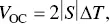
when the p ‐ and n ‐type thermoelectric materials have the same absolute Seebeck coefficient value. When the system is connected to an external load and form a close circuit, the open‐circuit voltage dissipated on the external load and the internal resistance ( R in) that includes the resistances of materials, contacts, and wires,
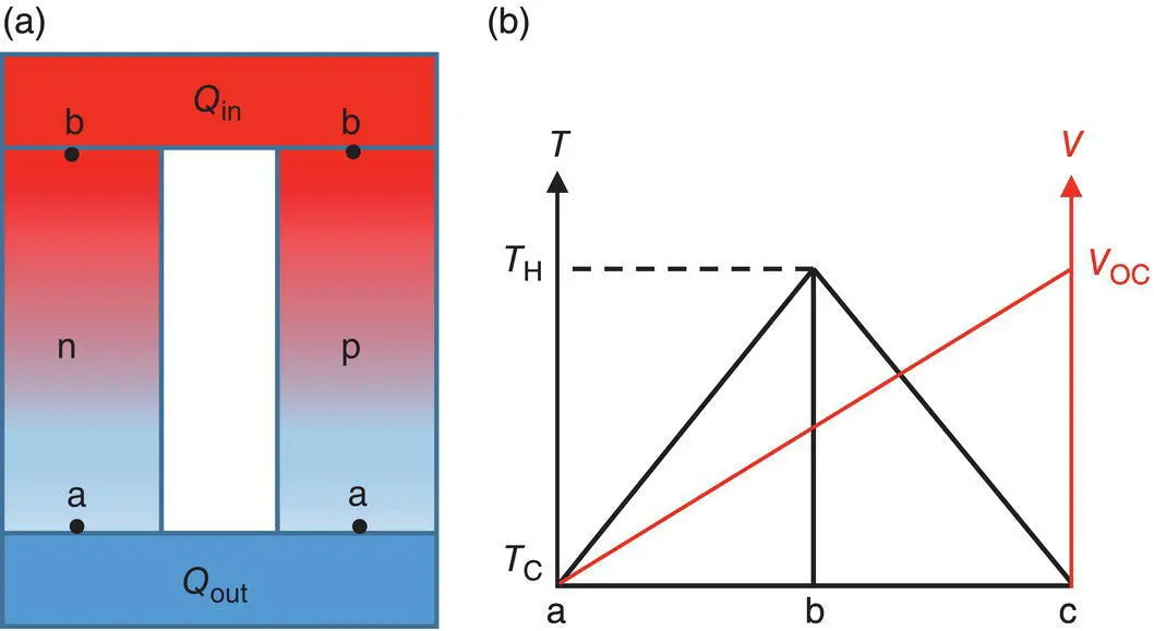
Figure 1.22 (a) A thermoelectric generator with n ‐ and p ‐type legs. Heat transfer (Q in) into the thermoelectric legs from the hot side and heat transfer (Q out) out from the cold side. (b) Temperature and voltage profiles at open‐circuit condition.
(1.53) 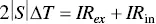
The current through the circuit can be obtained as
(1.54) 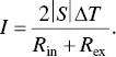
Thus, the equation for the power is given by
(1.55) 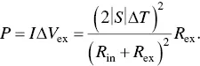
By introducing a parameter  the equation (1.55)becomes
(1.56) 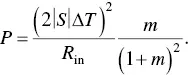
When R in= R ex, the external load has the maximum power ( P max),
(1.57) 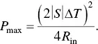
Figure 1.23shows the variations of the output power with the external load resistance at different temperature differences [34]. The output power increases when the temperature difference increases. However, at the optimal output power, the corresponding load resistance is independent of the temperature difference.
The equation for the efficiency ( η ) can be obtained as it is the ratio of the output power to the incident heat ( Q in) into the system,
(1.58) 
Heat energy transport through this system with the two thermoelectric legs, p ‐ and n ‐type legs. The incident heat at the hot side is balanced by the Peltier effect at the contacts between the legs and the metal electrodes, and the heat transfers due to the temperature gradient. The heat transferring from the hot to the cold side is equivalent to the Peltier effect at the contacts and the heat out from the cold side. Thus, the equations at the two boundaries (hot and cold side) are given by
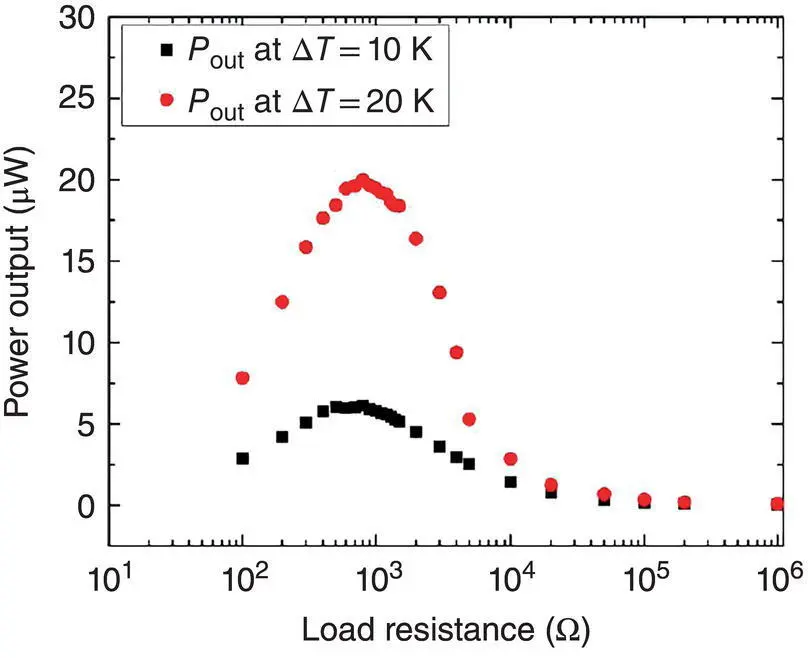
Figure 1.23 Variations of the power output of a TEG with the load resistance at Δ T = 10 and 20 K.
Source: Madan et al. [34]. © American Chemical Society.
(1.59) 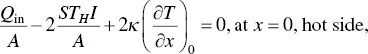
(1.60) 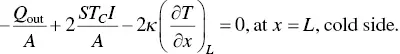
By ignoring the Thomson effect, the equation (1.50)for one leg becomes
(1.61) 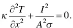
Using the boundary conditions of T (0) = T Hand T ( L ) = T C, the following equations can be obtained,
(1.62) 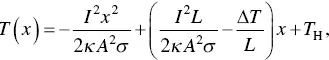
(1.63) 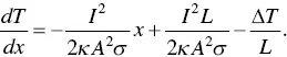
At x = 0,
(1.64) 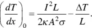
Using Eq. (1.54)in Eq. (1.59), the expression for Q incan be obtained as below,
(1.65) 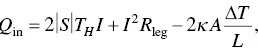
where  is the intrinsic resistance of one leg.
In terms of Eqs. (1.54), (1.56), and (1.65), the conversion efficiency is given by
(1.66) 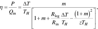
where z is the figure of merit of the thermoelectric module,
(1.67) 
The internal resistance ( R in) includes the contact resistances and the resistances of the thermoelectric legs. When the contact resistances are neglected, z becomes the figure of merit ( Z ) of the materials,
Читать дальшеИнтервал:
Закладка:
Похожие книги на «Flexible Thermoelectric Polymers and Systems»
Представляем Вашему вниманию похожие книги на «Flexible Thermoelectric Polymers and Systems» списком для выбора. Мы отобрали схожую по названию и смыслу литературу в надежде предоставить читателям больше вариантов отыскать новые, интересные, ещё непрочитанные произведения.


Обсуждение, отзывы о книге «Flexible Thermoelectric Polymers and Systems» и просто собственные мнения читателей. Оставьте ваши комментарии, напишите, что Вы думаете о произведении, его смысле или главных героях. Укажите что конкретно понравилось, а что нет, и почему Вы так считаете.