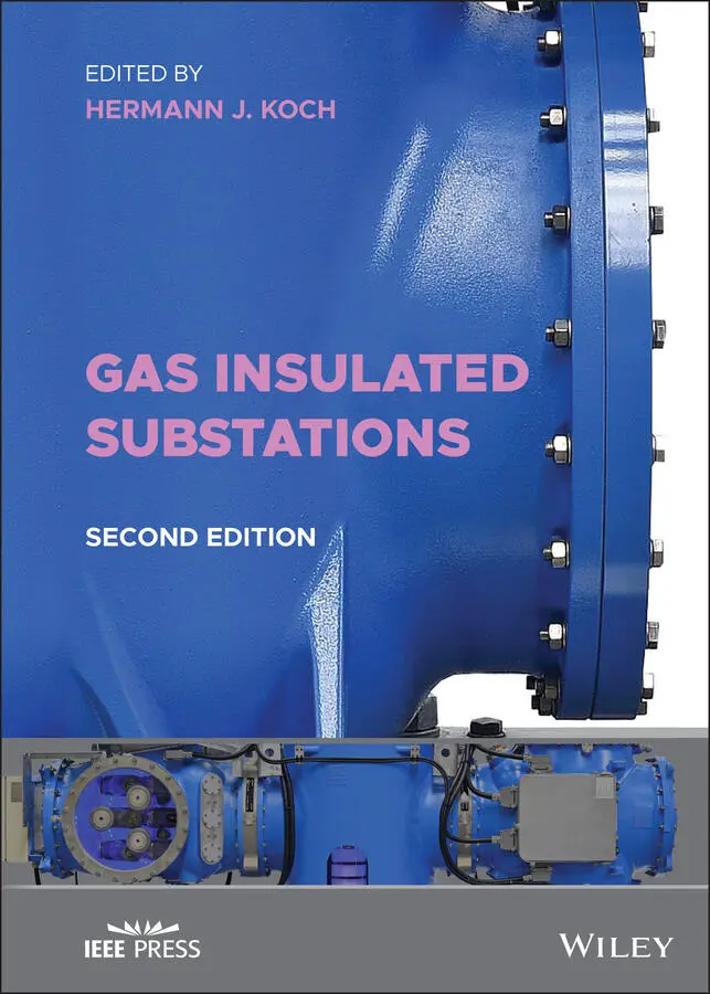
Gas Insulated Substations
Здесь есть возможность читать онлайн «Gas Insulated Substations» — ознакомительный отрывок электронной книги совершенно бесплатно, а после прочтения отрывка купить полную версию. В некоторых случаях можно слушать аудио, скачать через торрент в формате fb2 и присутствует краткое содержание. Жанр: unrecognised, на английском языке. Описание произведения, (предисловие) а так же отзывы посетителей доступны на портале библиотеки ЛибКат.
- Название:Gas Insulated Substations
- Автор:
- Жанр:
- Год:неизвестен
- ISBN:нет данных
- Рейтинг книги:3 / 5. Голосов: 1
-
Избранное:Добавить в избранное
- Отзывы:
-
Ваша оценка:
Gas Insulated Substations: краткое содержание, описание и аннотация
Предлагаем к чтению аннотацию, описание, краткое содержание или предисловие (зависит от того, что написал сам автор книги «Gas Insulated Substations»). Если вы не нашли необходимую информацию о книге — напишите в комментариях, мы постараемся отыскать её.
Gas Insulated Substations (GIS)
Gas Insulated Substations — читать онлайн ознакомительный отрывок
Ниже представлен текст книги, разбитый по страницам. Система сохранения места последней прочитанной страницы, позволяет с удобством читать онлайн бесплатно книгу «Gas Insulated Substations», без необходимости каждый раз заново искать на чём Вы остановились. Поставьте закладку, и сможете в любой момент перейти на страницу, на которой закончили чтение.
Интервал:
Закладка:
4 Chapter 4Figure 4.1 Gas density monitor mounted on the GIS enclosure. This type displ...Figure 4.2 Photos showing a variety of couplers used for PD detection in GIS...Figure 4.3 Indoor local control cabinetFigure 4.4 Outdoor local control cabinetFigure 4.5 Mimic diagramFigure 4.6 Local control cabinet, door open viewFigure 4.7 Local control cabinet, cable termination viewFigure 4.8 IEC 61850 relation to other IEC standardsFigure 4.9 Complex functions to be transferred in core pieces of logical nod...Figure 4.10 Logical nodes of a GIS bayFigure 4.11 Location of control and communication devices of GIS (Example 1)...Figure 4.12 Typical example of a communication network inside a GISFigure 4.13 Opening/closing command to intelligent switchgearFigure 4.14 Calculation of intelligent switchgear operating timesFigure 4.15 Measurement of the operating timeFigure 4.16 Timing of opening/closing command to intelligent switchgear [7]...Figure 4.17 Opening operation of an intelligent circuit breaker [7]Figure 4.18 Closing operation of an intelligent circuit breaker [7]
5 Chapter 5Figure 5.1 Overview of dielectric tests for GIS [1, 6]Figure 5.2 Example of a dielectric type test of a GISFigure 5.3 Test setup for the temperature rise test: (left) thermocouples ar...Figure 5.4 Generator for short‐circuit testingFigure 5.5 SF 6tightness testFigure 5.6 Low‐ and high‐temperature test in a climate chamberFigure 5.7 Pressure coordination of enclosures and pressure‐relief device [1...Figure 5.8 Leakage test as part of routine testingFigure 5.9 Pressure and tightness test of cast aluminum enclosuresFigure 5.10 Accumulation‐type test using plastic sheets or bagsFigure 5.11 Dimensional clearances during high‐voltage AC withstand tests...
6 Chapter 6Figure 6.1 Example site survey sketch (for illustration only)Figure 6.2 Conex boxFigure 6.3 Gas bus off‐loading and storage for large amounts of SF 6Figure 6.4 GIS crates and bushings storage on siteFigure 6.5 Gas weight record and sketchFigure 6.6 SF 6project gas inventoryFigure 6.7 Bolt head marked as torque checkedFigure 6.8 GIS assembly moved into place by mobile craneFigure 6.9 GIS breaker moved into place by building bridge craneFigure 6.10 GIS breaker slide into position on roller pads using come‐alongs...Figure 6.11 Gas cart for vacuum and filling GISFigure 6.12 Typical vacuum manifoldFigure 6.13 Vacuum rise testFigure 6.14 Gas zone processing tagsFigure 6.15 Example of tagged gas zone adjacent to the valveFigure 6.16 Assembly of GIS circuit breakersFigure 6.17 Assembly of the bus barFigure 6.18 Assembly of voltage transformersFigure 6.19 Cable termination to the GISFigure 6.20 GIS connection to the overhead lineFigure 6.21 Example of gas zone barrier insulator location (dark band)Figure 6.22 One example a GIS disconnect lockout methodFigure 6.23 One example a GIS disconnect lockout methodFigure 6.24 Flange gas leakage testFigure 6.25 Gas zone leakage detectorsFigure 6.26 SF 6gas analyzerFigure 6.27 Circuit breaker stroke measurementFigure 6.28 Circuit breaker timing equipmentFigure 6.29 Resonance high‐voltage test equipmentFigure 6.30 Tool rack (above framed one line and gas zone drawings)
7 Chapter 7Figure 7.1 GIS circuit breakerFigure 7.2 Circuit breaker mechanism control cabinetFigure 7.3 GIS disconnect switchesFigure 7.4 GIS ganged disconnect switchFigure 7.5 Disconnect motor operator isolation switchFigure 7.6 Switch position indicator – semaphoreFigure 7.7 Switch position indicator – targetFigure 7.8 Switch position indicator – stopsFigure 7.9 GIS ground switchFigure 7.10 GIS fast acting ground switchFigure 7.11 GIS inductive voltage transformerFigure 7.12 GIS inductive current transformers in circuit breaker bushing tu...Figure 7.13 GIS viewports – AFigure 7.14 GIS viewports – B with coversFigure 7.15 Gas density monitor and fill valveFigure 7.16 GIS gas density monitorFigure 7.17 GIS gas fill valveFigure 7.18 GIS pressure reliefFigure 7.19 Local control cabinet – outdoorFigure 7.20 Local control cabinet – indoorFigure 7.21 Gas zone schematic exampleFigure 7.22 GIS leak detection using liquid snoopFigure 7.23 Leaky bushing repair (a) – cast bushing fitting (b) – enclosure ...Figure 7.24 Interface between two GIS of different sizes: old GIS (right), n...Figure 7.25 X‐ray radiography example of an existing GIS at the interface lo...Figure 7.26 Typical life cycle behavior of GIS equipmentFigure 7.27 Old GIS from the first‐generation design in the 1960sFigure 7.28 New‐generation design of todayFigure 7.29 Maximum protection from touching high‐voltage parts by grounded ...Figure 7.30 Latest design of compact design GIS with operation drives and ga...Figure 7.31 Extension of an existing GIS with one three‐phase bay of an indo...Figure 7.32 Extension of an existing GIS with one three‐phase bay of an outd...Figure 7.33 Old GIS beaker replacement: (left) before and (right) afterFigure 7.34 Replacement of old voltage transformers: (left) CCVT and (right)...Figure 7.35 Relationship between the rated maximum temperature ( T ), I 2 R lo...Figure 7.36 Relationship between exponential heating and the overload, rated...Figure 7.37 Direct transformer connection photo 1 substation overview, photo...Figure 7.38 Project planningFigure 7.39 Electrical configuration before the faultFigure 7.40 Fault damage at the time of cable energizationFigure 7.41 Left photo: outer enclosure; right photo: arc damage at the cond...Figure 7.42 Tag line – correct bus rigging using tag lines and support perso...
8 Chapter 8Figure 8.1 Single bus arrangement three‐phase insulatedFigure 8.2 Double bus arrangement three‐phase insulatedFigure 8.3 Ring bus arrangement three‐phase insulatedFigure 8.4 Typical H‐scheme (H5) arrangement three‐phase insulatedFigure 8.5 Breaker and a half arrangement single‐phase insulatedFigure 8.6 Layout of the 500 kV GIS and control buildingFigure 8.7 Overview of the electrical layout 500 kV GIS/115 kV AISFigure 8.8 Physical arrangement of the 500 kV GISFigure 8.9 Electrical layout of the 115 kV breaker and half arrangement, sim...Figure 8.10 Physical layout of the 115 kV breaker and half arrangement subst...Figure 8.11 Gas zone scheme, simplifiedFigure 8.12 Typical gas filling pressure of the different GIS compartments...Figure 8.13 View into the GIS hall with breaker and half schemeFigure 8.14 View of the GIS lightweight, low‐cost design buildingFigure 8.15 Wall penetration by buses for connection to overhead lines by SFFigure 8.16 Wall penetrations and cable potheads with surge arresters on the...Figure 8.17 Connection of overhead line to the GIS through SF 6gas‐to‐air bu...Figure 8.18 Local control cabinetsFigure 8.19 Bird’s eye view of the 345 kV GISFigure 8.20 View into the 345 kV GIS buildingFigure 8.21 Front view of the 345 kV GIS bays including cubicle of the circu...Figure 8.22 Local control cabinet (LCC) in a separate control room for the 3...Figure 8.23 Local control cabinet (LCC) internal for the 345 kV GISFigure 8.24 Electrical layout shown by the gas compartment schematic, simpli...Figure 8.25 Physical layout of the 69 kV GIS equipment, simplifiedFigure 8.26 Side views of three different bay arrangements, simplifiedFigure 8.27 View of the one‐bay 69 kV GIS, principle designFigure 8.28 Local control cabinetFigure 8.29 Substation building for GIS in a residential areaFigure 8.30 One‐line schematic showing the electrical ring bus switching sch...Figure 8.31 Old 115 kV substation before replacementFigure 8.32 The 115 kV GIS container installationFigure 8.33 View inside the container with the GIS on the left and the LCCs ...Figure 8.34 View of the 115 kV GIS container and the transformerFigure 8.35 View of the 115 kV GIS substation from the streetFigure 8.36 View of 115 kV outdoor GISFigure 8.37 Electrical single‐line scheme of the 345 kV indoor GISFigure 8.38 Top view of the GIS, transformer, and cable connection arrangeme...Figure 8.39 View into the GIS hallFigure 8.40 View at wall bushings on the steel supportFigure 8.41 View of the walkway and local control cabinets in front of the G...Figure 8.42 View from the rear side of the GIS with directly connected cable...Figure 8.43 Outside view of the GIS buildingFigure 8.44 The 115 kV indoor GIS layoutFigure 8.45 Masonry construction type building of the 115 kV GISFigure 8.46 Side view of three different baysFigure 8.47 View into the 115 kV GIS buildingFigure 8.48 View of the 115 kV GIS inside the buildingFigure 8.49 View of the medium voltage 25 kV GIS and 115/25 kV transformer b...Figure 8.50 Total view of the 115 kV/12 kV indoor GISFigure 8.51 Overview of the single‐line diagram of the 69 kV indoor GISFigure 8.52 Top view of the 69 kV indoor GIS assemblyFigure 8.53 Side view of the 69 kV indoor GIS assemblyFigure 8.54 Single bay GIS with vertical three‐phase circuit breaker enclosu...Figure 8.55 View of 69 kV indoor GIS assembly with vertical three‐phase insu...Figure 8.56 One‐line diagram of the 138 kV outdoor GISFigure 8.57 Electrical layout of the 230 kV outdoor GISFigure 8.58 Typical layout of 138/230 kV GIS to transformer connection with ...Figure 8.59 Side view of the substation with the 138 kV GISFigure 8.60 Electrical layout of the 500 kV single‐phase encapsulated GIS, s...Figure 8.61 Physical layout of the 500 kV indoor GISFigure 8.62 Graphical view of the extension of one manufacturer’s old‐genera...Figure 8.63 Photographs of the extension of one manufacturer’s old‐generatio...Figure 8.64 Graphical view of the extension of an old‐generation GIS with a ...Figure 8.65 Photographs of the extension of an old‐generation GIS with a new...Figure 8.66 Outgoing buses are shown below the building gradeFigure 8.67 One‐line diagram for two parts of the 69 kV GIS, simplified draw...Figure 8.68 Side elevation of the GIS with SF 6gas‐to‐air bushing, simplifie...Figure 8.69 Plan view of the 69 kV GIS substation, simplified drawingFigure 8.70 Side elevation of the 69 kV GIS with underground cable interface...Figure 8.71 Side elevation of the 69 kV GIS bay with circuit breaker and und...Figure 8.72 Compact design of the 69 kV GISFigure 8.73 Underground substation for 69 kV below a city parkFigure 8.74 Electrical single‐line scheme of the 69 kV underground GISFigure 8.75 Top view of the 69 kV underground GISFigure 8.76 Side view of the cable bayFigure 8.77 Entrance to the underground substationFigure 8.78 Emergency exit of the underground substation in the parkFigure 8.79 Outside view of the lightweight GIS buildingFigure 8.80 Inside view of the 8 bays GIS during erection. Front sideFigure 8.81 Inside view of the 8 bays GIS during erection. Rear sideFigure 8.82 View to vertical circuit breaker enclosures with connected groun...Figure 8.83 View to outgoing three phase bus lines. Rear sideFigure 8.84 History of BergenFigure 8.85 Conclusion of the site evaluationFigure 8.86 Electrical layout of the substationFigure 8.87 Physical layout of the substationFigure 8.88 Camera system for disconnects and grounding switchesFigure 8.89 Gas density monitoring systemFigure 8.90 UHF partial discharge monitoring systemsFigure 8.91 Providing the foundationFigure 8.92 Erection of the GIS buildingFigure 8.93 GIS under constructionFigure 8.94 GIS installation completed (left) and walkway in GIS bays (right...Figure 8.95 Bergen switching station, 230 kV, 80 kA with gantry supportsFigure 8.96 Gas‐insulated bus section to connect the GIS in the building to ...Figure 8.97 Bergen switching station aerial viewFigure 8.98 Left: top view of city center, right: possible route of electric...Figure 8.99 Left: GIL laid in an open trench, Right: GIL laid under a concre...Figure 8.100 Left: GIL laid in a concrete tunnel, Right: GIL laid directly i...Figure 8.101 GIL laid in a squared tunnel of 2.4 m width and 2.6 m height...Figure 8.102 Overview Street House ConceptFigure 8.103 Upper: cross‐section Street House Concept, lower: detail concre...Figure 8.104 Left: Street House Concept with tall office towers, right: Stre...Figure 8.105 Cross‐section of Street House at junction point with parking se...Figure 8.106 Left: access roads and integration of building complex to stree...Figure 8.107 Safe electric power transmission lines using GIL below office b...Figure 8.108 Impression of street house complex with electric power transmis...Figure 8.109 City Junction North Line, black line: existing overhead line, o...Figure 8.110 Infrastructure at City Junction North LineFigure 8.111 Principal design of 245 kV XLPE power cableFigure 8.112 Principal design of 550 kV GIL laid in a tunnel [7, 8, 10]Figure 8.113 Example of 2 three‐phase circuits 550 kV in a tunnel with reser...Figure 8.114 Top view of City Junction North, solid lineFigure 8.115 Overview of routing obstacles along City Junction North LineFigure 8.116 Connecting point overhead line (OHL) to GIL in a tunnelFigure 8.117 Upper part: example of highway crossing tunnel between two shaf...Figure 8.118 Example of height deviation level between residential area and ...Figure 8.119 Example of narrow space between residential area and highway...Figure 8.120 Example of bridge above high junction street sectionFigure 8.121 Example of underground tunnel section at access road to highway...Figure 8.122 Example of large tunnel with four segments for 550 kV GIL and 2...Figure 8.123 Example of tunnel boring machineFigure 8.124 Principal laying process of GIL in a tunnel through access shaf...Figure 8.125 Upper part: example of ventilation of four GIL circuits in two ...Figure 8.126 Ventilation shaft to segmented tunnel and minimized visual impa...Figure 8.127 Ventilation and access shaft of GIL or cable tunnel integrated ...Figure 8.128 Assembly of GIL through tunnel shaft and pull into tunnelFigure 8.129 Lifting GIL segments to positions at tunnel steel structures...Figure 8.130 Containerized substation, 123 kVFigure 8.131 Containerized substation, 123 kV – extension is in extremely co...Figure 8.132 Single‐line substation layout of a 72.5 kV GIS mounted on a tru...Figure 8.133 Substation layout of a 72.5 kV GIS mounted on a truck trailer –...Figure 8.134 Mobile 420 kV GIS mounted on a truckFigure 8.135 Mobile 420 kV GIS connected in the substationFigure 8.136 Mobile high‐ and medium‐voltage substationFigure 8.137 Mobile high‐voltage GIS mounted on a truck trailer – electrical...Figure 8.138 Mobile high‐voltage GIS mounted on a truck trailer – T‐connecti...Figure 8.139 Mobile medium‐voltage GIS mounted on a truck trailer – cable co...Figure 8.140 Mobile high‐ and medium‐voltage GIS substation – multibay confi...Figure 8.141 Mobile 72.5 kV voltage GIS – 15 bays double bus bar configurati...Figure 8.142 Overview of a typical design of mixed technology switchgear (MT...Figure 8.143 Space requirement comparison of AIS, GIS, and MTS circuit break...Figure 8.144 MTS module 420/550 kV with CB/SW/CT combinationFigure 8.145 MTS 550 kV bay module with CB/SW/CT combination and vertical bu...Figure 8.146 MTS 145 kV double circuit breaker with circuit breaker, disconn...Figure 8.147 Compact substation – double outdoor cable bay of 145 kV, 31.5 k...Figure 8.148 Compact substation – double bay on the roof of a substation bui...Figure 8.149 Compact substation – single‐phase insulated bay of 230 kV, 50 k...Figure 8.150 Compact substation – three‐phase insulated outdoor bay of 132 k...Figure 8.151 Three‐phase insulated outdoor bay to connect a wind farm of 145...Figure 8.152 Single‐phase insulated outdoor bay used to sectionalize an air‐...Figure 8.153 Progress in size reduction, example of the 145 kV GISFigure 8.154 Construction of a Rogowski coilFigure 8.155 Principle of the Rogowski coilFigure 8.156 Application of a Rogowski coilFigure 8.157 Construction of a capacitive dividerFigure 8.158 Principle of a capacitive dividerFigure 8.159 Groundwater treatment, upper part: water level at underground b...Figure 8.160 High‐temperature fire of burning oil of transformerFigure 8.161 Separated ventilation for transformer and buildingFigure 8.162 Sprinkler system on the ceiling (left), water drainage system o...Figure 8.163 On the left photo, the fire protection control system is shown,...Figure 8.164 Fresh air outlet and dust cleaner, left: under the transformer,...Figure 8.165 Left: transformer‐encapsulated termination with XLPE at 110 kV,...Figure 8.166 Left: substation ventilation shaft from the basement of the bui...Figure 8.167 Reduced air exchange by using air conditioning, left: switchgea...Figure 8.168 Typical air conditioner system to compensate the heat released ...Figure 8.169 Heating exchanger from transformer oil to the building heater...Figure 8.170 Left: sound absorbing cover on the ceiling, right: sound absorb...Figure 8.171 Acoustic solutions for underground substation ventilationFigure 8.172 Use of surge arresters to protect from lightning strokes (left)...Figure 8.173 Substation control room next to the high‐voltage switchgear of ...Figure 8.174 Vicinity of people and public, left: at underground substations...Figure 8.175 Left: 145 kV and 3150 A high‐voltage GIS, right: 11 kV and 2000...Figure 8.176 Completely underground substation with a public park on the top...Figure 8.177 Semi‐underground substation in a sloop between street, public p...Figure 8.178 Underground substation with a public park on the topFigure 8.179 Substation building above ground in a city centerFigure 8.180 Substation in an exhibition area installed undergroundFigure 8.181 Substation under a park or green field in the city centerFigure 8.182 Substation under a square or plaza in the city centerFigure 8.183 Architectural solutions for substation in the city center, left...Figure 8.184 City center development, left: city view in 1980s, right: city ...Figure 8.185 City development with three new underground substationsFigure 8.186 Substation integrated at the convention centerFigure 8.187 Substation integrated in Financial District (left) and city cen...Figure 8.188 420 kV GIS substation for industrial aestheticsFigure 8.189 Example of a project execution schedule of an underground subst...Figure 8.190 Left 110/10 kV GIS Substation in the basement of a building com...Figure 8.191 Access shaft for 110/10 kV transformer 40 MVA at underground le...Figure 8.192 Access shaft for 110/10 kV transformer 40 MVA at underground le...Figure 8.193 330/132 kV Downtown Business District substation, left: locatio...Figure 8.194 330/132 kV Downtown Business District substation, left: four ba...Figure 8.195 Hydropower plant, left: Damn in a mountain valley, right: acces...Figure 8.196 Hydropower plant, left: Seven bays of 420 kV GIS, double busbar...Figure 8.197 Hydropower plant, dam overview in a remote mountainous area dif...Figure 8.198 Hydropower storage plant, left: connection to 245 kV power grid...Figure 8.199 Hydropower storage plant, left: entering the cavern through a t...Figure 8.200 Substation building at desert conditions 132/11 kV, left: subst...Figure 8.201 Residential area city substation 132/11 kV, left: overview of s...Figure 8.202 Three‐voltage‐level substation 1 of 11/66/220 kV, left: substat...Figure 8.203 Three‐voltage‐level substation 2 building of 11/66/220 kV inclu...Figure 8.204 Stadium substation left: stadium overview, with 110/10 kV GIS b...Figure 8.205 Prefabricated concrete slab under the grass floorFigure 8.206 Monument Park substation of 132 kV GIS, left: access to substat...Figure 8.207 City center transmission voltage substation 245 kV GIS, left: s...Figure 8.208 Schoolyard substation in a building basement, left: lifting sha...Figure 8.209 Schoolyard substation in a building basement, left: five 110 kV...Figure 8.210 Remote area substation with 362 kV GIS located in a mountain ca...Figure 8.211 Remote area substation, left: sketch of GIS in a cavern and a G...Figure 8.212 Futuristic harbor substation, left: multilevel substation build...
Читать дальшеИнтервал:
Закладка:
Похожие книги на «Gas Insulated Substations»
Представляем Вашему вниманию похожие книги на «Gas Insulated Substations» списком для выбора. Мы отобрали схожую по названию и смыслу литературу в надежде предоставить читателям больше вариантов отыскать новые, интересные, ещё непрочитанные произведения.


Обсуждение, отзывы о книге «Gas Insulated Substations» и просто собственные мнения читателей. Оставьте ваши комментарии, напишите, что Вы думаете о произведении, его смысле или главных героях. Укажите что конкретно понравилось, а что нет, и почему Вы так считаете.