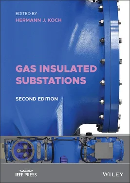
Gas Insulated Substations
Здесь есть возможность читать онлайн «Gas Insulated Substations» — ознакомительный отрывок электронной книги совершенно бесплатно, а после прочтения отрывка купить полную версию. В некоторых случаях можно слушать аудио, скачать через торрент в формате fb2 и присутствует краткое содержание. Жанр: unrecognised, на английском языке. Описание произведения, (предисловие) а так же отзывы посетителей доступны на портале библиотеки ЛибКат.
- Название:Gas Insulated Substations
- Автор:
- Жанр:
- Год:неизвестен
- ISBN:нет данных
- Рейтинг книги:3 / 5. Голосов: 1
-
Избранное:Добавить в избранное
- Отзывы:
-
Ваша оценка:
- 60
- 1
- 2
- 3
- 4
- 5
Gas Insulated Substations: краткое содержание, описание и аннотация
Предлагаем к чтению аннотацию, описание, краткое содержание или предисловие (зависит от того, что написал сам автор книги «Gas Insulated Substations»). Если вы не нашли необходимую информацию о книге — напишите в комментариях, мы постараемся отыскать её.
Gas Insulated Substations (GIS)
Gas Insulated Substations — читать онлайн ознакомительный отрывок
Ниже представлен текст книги, разбитый по страницам. Система сохранения места последней прочитанной страницы, позволяет с удобством читать онлайн бесплатно книгу «Gas Insulated Substations», без необходимости каждый раз заново искать на чём Вы остановились. Поставьте закладку, и сможете в любой момент перейти на страницу, на которой закончили чтение.
Интервал:
Закладка:
List of Illustrations
1 Chapter 1 Figure 1.1 Organization of the Substations Committee
2 Chapter 2 Figure 2.1 One of the first GIS installed in Berlin, Germany, in 1968 at Wit... Figure 2.2 Steel enclosure – inductive flange production Figure 2.3 Circuit breaker enclosure – three‐phase design of 110 kV Figure 2.4 110 kV GIS – double bus bar, three‐phase encapsulated, horizontal... Figure 2.5 380 kV horizontal GIS – three‐phase double bus bar and single‐pha... Figure 2.6 Steel enclosure manufacturing process Figure 2.7 Aluminum enclosure manufacturing Figure 2.8 (a) 145 kV GIS – single‐phase encapsulated and horizontal circuit... Figure 2.9 (a) 110 kV GIS – vertical circuit breaker and three‐phase enclosu... Figure 2.10 (a) 500 kV GIS – horizontal single‐phase circuit breaker and two... Figure 2.11 Self‐blast interruption unit – 1973 first patent Figure 2.12 Two‐cycle circuit breaker – anticompression cylinder – 1977 firs... Figure 2.13 Double valve interruption unit – 1985 first patents – low power ... Figure 2.14 Hydraulic drive for circuit breakers – until 2000 Figure 2.15 Spring drive for circuit breakers – since 2000 Figure 2.16 Reduction in size of GIS – 145 kV rated voltage Figure 2.17 Extension of 110 kV GIS – 110kV rated voltage. Extension of firs... Figure 2.18 Reduction of SF 6– gas weight reduction Figure 2.19 A coaxial system such as in GIS Figure 2.20 The maximum electric field inside a GIS remains near constant ov... Figure 2.21 An electron in an electric field is accelerated, creating an ava... Figure 2.22 Mean free path is the mean distance a particle (electron) travel... Figure 2.23 Sulfur hexafluoride has twice the collision diameter of nitrogen... Figure 2.24 Increasing the gas design by six times has a large impact on red... Figure 2.25 A void in a solid insulator will cause a local field enhancement... Figure 2.26 World‐wide installed GIS Figure 2.27 Comparison of the GIS service Figure 2.28 Single‐ and three‐phase designs of GIS Figure 2.29 GIS maintenance strategies Figure 2.30 Failure distribution on voltage levels Figure 2.31 Indoor and outdoor GIS failure distribution Figure 2.32 GIS component failure distribution Figure 2.33 Failure numbers of GIS related to age Figure 2.34 Comparison of the failure rates of the GIS and AIS Figure 2.35 Ladders and platforms in GIS Figure 2.36 Gas density monitoring indicator Figure 2.37 UHF antenna connector for PD monitoring Figure 2.38 Compensation of thermal expansion. (a) Thermal expansion between... Figure 2.39 Direct cable connection to GIS at 110 kV and single‐phase insula... Figure 2.40 View of a typical floor inside a GIS building Figure 2.41 Ground/earth connection of GIS using bolts or a steel bar (Halfe... Figure 2.42 Three‐phase GIS enclosure currents Figure 2.43 Single‐phase GIS enclosure currents Figure 2.44 Circuit breaker and GIS bay grounding Figure 2.45 Buildings Figure 2.46 SF6 gas‐to‐cable connections Figure 2.47 Steel structures Figure 2.48 Molecular structure of sulfur hexafluoride (SF 6) Figure 2.49 Greenhouse effect Figure 2.50 Arc current of SF 6, with SF 6gas‐to‐air gas mixture and air Figure 2.51 SF 6sales by end use of 2003 Figure 2.52 Reduction of the use of SF 6 Figure 2.53 SF 6handling and recovering processes Figure 2.54 Reuse program of SF 6for normal and special cases Figure 2.55 Closed loop handling symbol Figure 2.56 SF 6purifying on‐site Figure 2.57 SF 6recycling to ASTM D2472 [65] new gas Figure 2.58 Reuse program – exceptional case Figure 2.59 Incineration of SF 6 Figure 2.60 Commissioning or recommissioning of SF 6 Figure 2.61 For topping‐up of SF 6 Figure 2.62 SF 6refilling of SF 6 Figure 2.63 Moisture content/dew point of SF 6 Figure 2.64 Measurement of SF 6 Figure 2.65 Quantity of reactive gaseous of SF 6 Figure 2.66 Sampling and shipment of SF 6 Figure 2.67 Recovery and reclaiming of nonarced and/or normally arced of SF 6 Figure 2.68 Heavily arced of SF 6 Figure 2.69 End‐of‐life disposal of SF 6 Figure 2.70 EPA Memorandum of Understanding Figure 2.71 Gas‐control scheme (e.g., with information about volume and pres... Figure 2.72 Training of SF 6handling Figure 2.73 General purpose SF 6reclaimer of SF 6 Figure 2.74 Filter types of SF 6 Figure 2.75 Equipment for SF 6measurement of SF 6 Figure 2.76 Sniffing device of SF 6 Figure 2.77 Density meter of SF 6 Figure 2.78 Small equipment for Evacuation, Filling and Refilling of SF 6 Figure 2.79 Large equipment for evacuation, filling and refilling of SF 6 Figure 2.80 Storage of SF 6 Figure 2.81 Gas recovery of SF 6for a small and a large enclosure Figure 2.82 Measuring protocol of gas recovery of SF 6 Figure 2.83 Energy supply without/with SF 6technology – city of Würzburg Figure 2.84 AIS and GIS network structures Figure 2.85 Result of environmental impact of AIS and GIS solutions Figure 2.86 Kyoto Protocol – change from 2008 to 2012 in comparison to 1990... Figure 2.87 145 kV SF 6GIS with 7 bays Figure 2.88 Impression on the influence of high GWP values: 1200 beech trees... Figure 2.89 SF 6emission rate reduced but total SF 6capacity increases Figure 2.90 Typical type test set up for high‐voltage test using SF 6 Figure 2.91 GIS installation with SF 6filling on‐site Figure 2.92 Use of SF 6in a closed cycle for the complete life cycle of GIS ... Figure 2.93 Characteristics of different alternative gases for GIS Figure 2.94 170 kV GIS air‐insulated circuit breaker in an air insulation de... Figure 2.95 Left: 72/84 kV dead tank VI circuit breaker with synthetic air i... Figure 2.96 145 kV live tank VI circuit breaker with N 2insulation, 2010 Figure 2.97 Left: 170 kV GIS with flouroketone for the circuit breaker and f... Figure 2.98 Left: 145 kV GIS using flouronitrile for insulation including th... Figure 2.99 Transition from only SF 6to multiple gases Figure 2.100 Insulating gases used in transmission (left of line) and distri...Figure 2.101 Typical Outdoor AIS substation ( Source [96])Figure 2.102 Typical Dead Tank Compact Switchgear (DTC) components. 1. Bushi...Figure 2.103 Cross section and physical assembly of 363kV GIS Figure 2.104 Space savings using GIS instead of AIS Figure 2.105 GIS substation under a park in a city centerFigure 2.106 GIS substation within a historical building in the old part of ...Figure 2.107 330 kV indoor GIS substation at −50 °C (−58°) F outdoor tempera...Figure 2.108 Typical AIS equipment installation Figure 2.109 GIS installation by a complete bay Figure 2.110 Reduction of SF 6GIS from the year 1970 until 2016 for a model ...Figure 2.111 GIS installation in architecturally enhanced building (Used wit...Figure 2.112 Coaxial design principal of gas‐insulated switchgear, r c= rad...
3 Chapter 3Figure 3.1 Steel encapsulated GISFigure 3.2 Straight conductor graphicFigure 3.3 Three‐phase bus barFigure 3.4 Classic three‐phase cross section of a 72.5–170 kV GIS and a phot...Figure 3.5 Three‐phase circuit breaker enclosure up to 72.5 kVFigure 3.6 Three‐position, three‐phase encapsulated switch (a) four flange e...Figure 3.7 Three‐phase encapsulated high‐speed ground switch (a) enclosure w...Figure 3.8 Three‐phase encapsulated voltage transformer of 145 kV (a) enclos...Figure 3.9 Three‐phase encapsulated current transformer of 145 kV, (a) enclo...Figure 3.10 Three‐phase overhead line connection moduleFigure 3.11 Three‐phase overhead line connection module (cross section)Figure 3.12 Three‐phase (3a) and single phase (3b) encapsulated cable connec...Figure 3.13 Three‐phase encapsulated surge arrestersFigure 3.14 Three‐phase encapsulated bus bar for upto145 kV, (a) enclosure w...Figure 3.15 Typical GIS modules of single‐phase encapsulation of 245 kV and ...Figure 3.16 Circuit breaker single‐phase encapsulated module for 245 kV and ...Figure 3.17 Disconnector and ground single‐phase encapsulated switch of 245 ...Figure 3.18 Load‐break disconnector single‐phase encapsulated switch of 245 ...Figure 3.19 Current transformer module (a) cut open module with conductor, s...Figure 3.20 Voltage transformer moduleFigure 3.21 Progress of GIS development of a 145 kV GIS for size, space, and...Figure 3.22 Field experiences – feedback for the developmentFigure 3.23 Typical GIS factoryFigure 3.24 Vacuum testing of insulatorsFigure 3.25 Electrode preparation of insulatorsFigure 3.26 Conical gastight insulatorsFigure 3.27 Casting resin equipment for operation rods and tubesFigure 3.28 Machinery of operation rods and tubesFigure 3.29 Machinery center for enclosuresFigure 3.30 Cleaning and degreasing of enclosuresFigure 3.31 Test equipment for routine pressure and gas tightness test of en...Figure 3.32 Enclosures ready for routine tests of pressure and gas tightness...Figure 3.33 Hydro pressure test of enclosuresFigure 3.34 Painting of enclosuresFigure 3.35 Preassembly of a circuit breaker with capacitor and resistorFigure 3.36 Preassembly of a hydraulic drive of a circuit breakerFigure 3.37 Final assembly hallFigure 3.38 Typical detailed one‐line diagram of a single bay of GISFigure 3.39 GIS circuit breakerFigure 3.40 Typical coupling contact arrangementFigure 3.41 Typical disconnect switch enclosure arrangementFigure 3.42 Typical maintenance grounding switch enclosure arrangementFigure 3.43 Typical fast‐acting grounding switch enclosure arrangementFigure 3.44 Typical gas zone diagram for one GIS bayFigure 3.45 Typical current transformer assemblyFigure 3.46 Typical inductive voltage transformer assemblyFigure 3.47 Typical single‐phase metal‐enclosed surge arrester assemblyFigure 3.48 Typical SF 6gas‐to‐air bushing assemblyFigure 3.49 Typical GIS to cable connection assemblyFigure 3.50 Typical GIB connection assemblyFigure 3.51 Typical expansion joint assemblyFigure 3.52 Typical transformer termination module arrangementFigure 3.53 Three‐phase insulated current transformer for up to 145 kV (a) e...Figure 3.54 Single‐phase insulated current transformer of 245 kV (a) enclosu...Figure 3.55 Three‐phase voltage transformer for voltages up to 145 kV (a) en...Figure 3.56 Single‐phase insulated voltage transformer for voltages of 245 k...Figure 3.57 Typical direct connection between a power transformer and GIS fo...Figure 3.58 Typical standard dimensions for a typical direct connection betw...Figure 3.59 Typical standard orientation of fixing holes (Simplified drawing...Figure 3.60 Fluid‐filled cable connection assembly – typical arrangement. (S...Figure 3.61 Fluid‐filled cable connection – typical assembly dimensions. (Si...Figure 3.62 Dry type cable connection assembly – typical arrangement. (Simpl...Figure 3.63 Dry type cable connection assembly – typical assembly dimensions...Figure 3.64 Cable termination three‐phase GIS enclosure 69 kV GIS, 1380kcmil...Figure 3.65 345kV Transmission Line transition to the 4000 A, 50 kA gas insu...Figure 3.66 345kV gas insulated Transmission Line (GIL) transition to the 40...Figure 3.67 Gas‐insulated surge arresters connected directly to the GIS bus...Figure 3.68 Three‐phase insulated passive bus ductFigure 3.69 Three‐phase insulated active bus ductFigure 3.70 Single‐phase insulated bus duct on the craneFigure 3.71 Single‐phase insulated passive bus ductFigure 3.72 Single‐phase insulated bus duct connection to overhead lines out...Figure 3.73 Single‐phase insulated bus duct to connect overhead lines with w...Figure 3.74 Single‐phase insulated bus duct connection to overhead lines wit...Figure 3.75 Single‐phase insulated bus duct connection to circuit breakers...Figure 3.76 Single‐phase insulated bus duct connection to transformersFigure 3.77 Single‐phase insulated bus duct connection to cablesFigure 3.78 Single‐phase insulated bus duct connection to cables with overvo...Figure 3.79 Single‐phase insulated bus duct to underpass overhead lines insi...Figure 3.80 Single‐phase insulated bus duct to underpass overhead lines outs...Figure 3.81 Single‐phase insulated bus duct above ground installed at low st...Figure 3.82 Single‐phase insulated bus duct above ground installation at hig...Figure 3.83 Single‐phase insulated bus duct above ground installation with d...Figure 3.84 Single‐phase insulated bus duct above ground installation at con...Figure 3.85 Single‐phase insulated bus duct above ground installation at con...Figure 3.86 Single‐phase insulated bus duct above ground installation to cro...Figure 3.87 Single‐phase insulated bus duct laid in a trench inside a substa...Figure 3.88 Single‐phase insulated bus duct laid in a trench outside a subst...Figure 3.89 Single‐phase insulated bus duct laid in a trench crossing a high...Figure 3.90 Single‐phase insulated bus duct double system laid in a horizont...Figure 3.91 Single‐phase insulated bus duct double system laid in a horizont...Figure 3.92 Single‐phase insulated bus duct double system laid in a horizont...Figure 3.93 Single‐phase insulated bus duct double system laid in a tunnel a...Figure 3.94 Single‐phase insulated bus duct double system laid in a vertical...Figure 3.95 Single‐phase insulated bus duct single system directly buried wi...Figure 3.96 Single‐phase insulated bus duct two‐phase test loop directly bur...Figure 3.97 Single‐phase insulated bus duct single‐phase test section direct...Figure 3.98 Single‐phase insulated bus duct double‐phase system directly bur...Figure 3.99 An 18‐m bus section being unloaded at the siteFigure 3.100 Final assembly of a 550 kV field joint. Locating pins are used ...Figure 3.101 Example of typical GIS architectures with gas zones of single b...Figure 3.102 Example of GIS diameter and bay in a breaker‐and‐a‐half scheme...Figure 3.103 Example of arrangement of enclosures and gas compartments
Читать дальшеИнтервал:
Закладка:
Похожие книги на «Gas Insulated Substations»
Представляем Вашему вниманию похожие книги на «Gas Insulated Substations» списком для выбора. Мы отобрали схожую по названию и смыслу литературу в надежде предоставить читателям больше вариантов отыскать новые, интересные, ещё непрочитанные произведения.
Обсуждение, отзывы о книге «Gas Insulated Substations» и просто собственные мнения читателей. Оставьте ваши комментарии, напишите, что Вы думаете о произведении, его смысле или главных героях. Укажите что конкретно понравилось, а что нет, и почему Вы так считаете.
