Phosphors for Radiation Detectors
Здесь есть возможность читать онлайн «Phosphors for Radiation Detectors» — ознакомительный отрывок электронной книги совершенно бесплатно, а после прочтения отрывка купить полную версию. В некоторых случаях можно слушать аудио, скачать через торрент в формате fb2 и присутствует краткое содержание. Жанр: unrecognised, на английском языке. Описание произведения, (предисловие) а так же отзывы посетителей доступны на портале библиотеки ЛибКат.
- Название:Phosphors for Radiation Detectors
- Автор:
- Жанр:
- Год:неизвестен
- ISBN:нет данных
- Рейтинг книги:3 / 5. Голосов: 1
-
Избранное:Добавить в избранное
- Отзывы:
-
Ваша оценка:
Phosphors for Radiation Detectors: краткое содержание, описание и аннотация
Предлагаем к чтению аннотацию, описание, краткое содержание или предисловие (зависит от того, что написал сам автор книги «Phosphors for Radiation Detectors»). Если вы не нашли необходимую информацию о книге — напишите в комментариях, мы постараемся отыскать её.
Phosphors for Radiation Detectors
Discover a comprehensive overview of luminescence phosphors for radiation detection Phosphors for Radiation Detection,
Phosphors for Radiation Detection
Phosphors for Radiation Detection
Phosphors for Radiation Detectors — читать онлайн ознакомительный отрывок
Ниже представлен текст книги, разбитый по страницам. Система сохранения места последней прочитанной страницы, позволяет с удобством читать онлайн бесплатно книгу «Phosphors for Radiation Detectors», без необходимости каждый раз заново искать на чём Вы остановились. Поставьте закладку, и сможете в любой момент перейти на страницу, на которой закончили чтение.
Интервал:
Закладка:
If we assume that P ( t ) is the probability per unit time of the decay of the metastable states N OSL( t ),
(1.61) 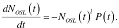
In this formula, l = 1 means a first‐order function. If each state n ( γ 1, γ 2, … γ m, t ) has its own probability function p ( γ 1, γ 2, … γ m) under the condition of l = 1, then
(1.62) 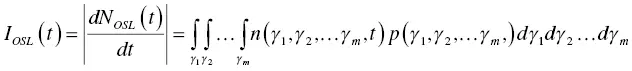
where we assume that no interaction between states occur. This formula has no time dependence of t , and if we would like to treat the probability time dependently, p ( γ 1, γ 2, … γ m, t ) should be used. The form of p depends on the stimulation methods such as TSL or OSL. For optical stimulation (OSL), we have
(1.63) 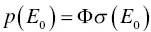
where E 0, Φ, and σ ( E 0) are the threshold of optical stimulation energy, optical stimulation intensity, and photoionization cross‐section, respectively. If m = 1, γ 1equals to E 0. In previous works [83, 84], photoionization cross‐section is expressed as
(1.64) 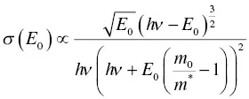
where hν is the energy of the incident photon of wavelength λ , m* is the charge carrier effective mass, and m 0is the rest of mass, respectively. There are several expressions of the photoionization cross‐section, and the more simple form [85] is
(1.65) 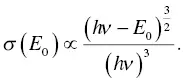
Photoionization is basically the same as the photoelectric (photoelectric absorption) effect, described in scintillation, but the energy assumed here is around visible photons (several eV).
Generally, stimulation intensity is a function of time, and can be expressed as
(1.66) 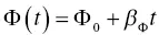
where Φ 0and β Φare a constant of stimulation and a proportional constant of the stimulation intensity if we assume a linear time dependence. If Φ ( t ) is constant, it represents a continuous wave OSL (CW‐OSL), and the OSL intensity becomes
(1.67) 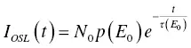
where t ( E 0) is 1/ p ( E 0). If Φ ( t ) is not constant, the situation is a linear modulation OSL (LM‐OSL), and the OSL intensity is
(1.68) 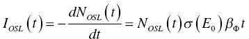
where we assume Φ 0= 0. Generally, we measure OSL in typical PL machines where the environment is free from any other light, and Φ 0= 0 is a valid assumption. In this case, the OSL intensity becomes
(1.69) 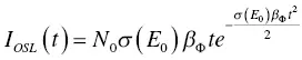
Based on these analytical equations, OSL intensity shows exponential decay under stimulation, and this is an important property to distinguish PL and RPL from OSL. If readers would like to study OSL in more detail, it will be better to read specialized books on OSL (for example, [3]).
Sections 1.4.2and 1.4.3describe common confirmed formulations of TSL and OSL, but up to now, a widely accepted formulation of RPL has not been obtained. RPL is treated as PL after carrier trapping phenomena, and general treatment of PL can be applied.
1.5 Relationship of Scintillation and Storage Luminescence
Up to now, scintillation (1.3)and ionizing radiation induced storage luminescence (1.4)have been carried out in different fields and by different people. However, these phenomena occur at the same time, and Figure 1.9describes the situation relating to luminescence by combining Figures 1.3and 1.8.
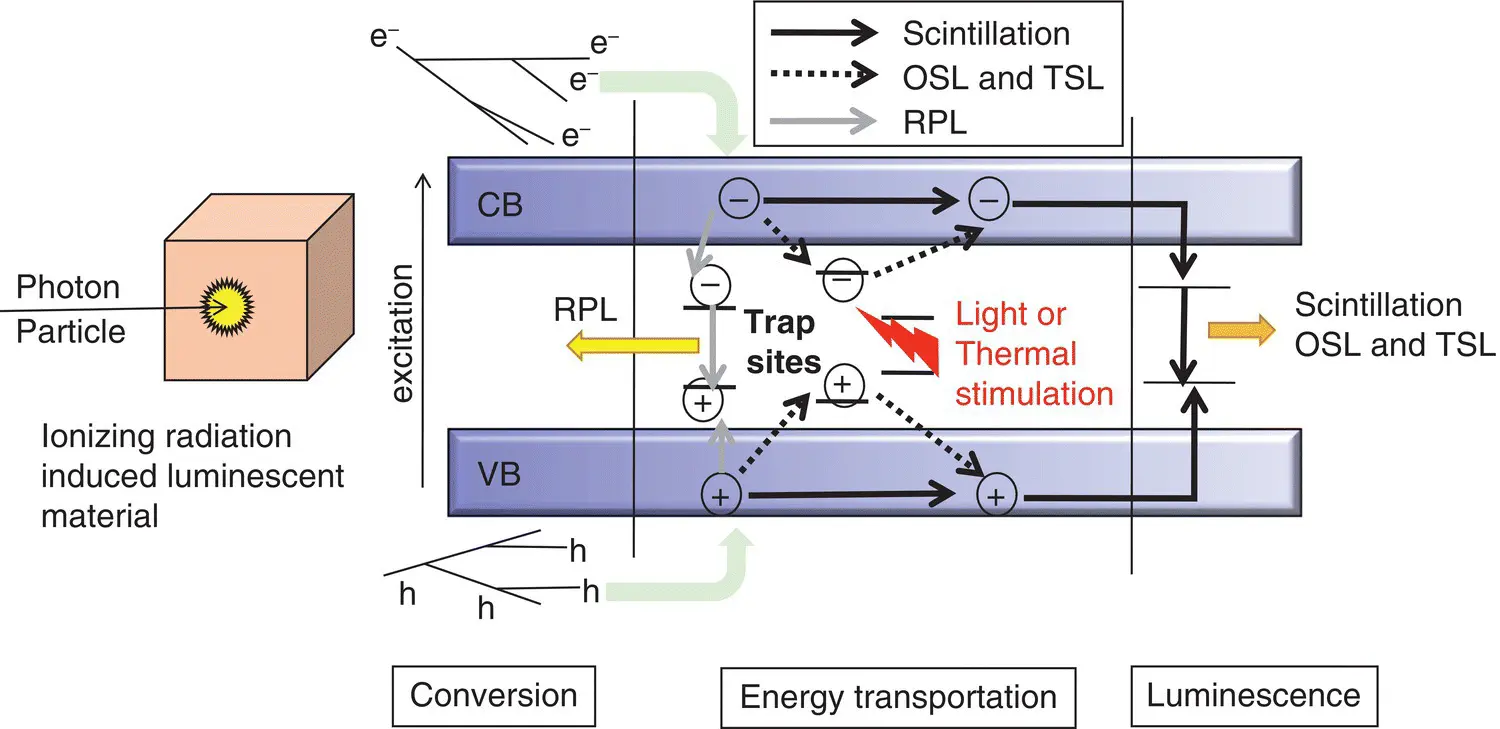
Figure 1.9 Typical emission mechanisms of scintillation, OSL, TSL, and RPL.
In addition to the luminescence phenomena described in these figures, some of the secondary electrons lose their energy thermally, and in such a case, we obtain no emissions. In the model of scintillation described in Section 1.3, it sometimes contains thermal energy dissipation as in Equation (1.15), but it does not consider that a significant amount of carrier is stored at trapping centers. In storage luminescence, such as TSL and OSL explained in Section 1.4, analysis is done by the rate equation, which does not consider how many carriers can reach the trapping centers, and scintillation is never assumed. The rate equation is only considered after the trapping (or generally luminescence) sites are occupied, so it cannot be used before the occupation. As commented above, scintillation and storage luminescence occur at the same time after the absorption of ionizing radiation. Therefore, in ionizing radiation induced luminescent materials, branching ratio of scintillation, storage luminescence, and thermal loss is important, and the branching probability of these phenomena can be expressed as
(1.70) 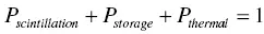
where P scintillation, P storage,and P thermalare the branching probabilities of secondary electrons to scintillation, storage luminescence, and thermal loss, respectively. It should be noted that the thermal energy loss is a very rough concept, and contains energy loss during any diffusion processes and relaxation processes at localized trapping and luminescence centers. Although the above equation is quite natural if we assume energy conservation, such a relation has not been considered historically because scintillator and dosimeters with storage phosphors have been investigated in different scientific fields.
The relationship among scintillation, storage luminescence, and thermal loss has been experimentally investigated recently by the author [82, 86–88]. In materials recognized as a phosphor, the ratio of thermal loss is relatively small, and in such a case, scintillation and storage luminescence should show an inverse proportional relationship. In order to confirm the validity of our assumption, we investigated the relationship of scintillation and storage luminescence intensities of materials which have different dopant concentrations. Figure 1.10shows a representative of the inverse proportional relationship of Ce differently doped CaF 2on OSL vs. scintillation. A clear inverse proportionality is observed, and confirms the validity of the assumption. A similar relationship has been confirmed in many material forms, including single crystal, glass, and ceramics in scintillation vs. OSL/TSL. In most luminous materials, we can observe such a relationship, but in the case of Ce‐doped LiCaAlF 6, we observed a positive proportional relationship [87]. Ce‐doped LiCaAlF 6is not luminous both in scintillation and storage luminescence, so we consider most of the absorbed energy will be converted to thermal loss. If we neglect the effect of thermal loss, a low temperature experiment will be helpful.
Читать дальшеИнтервал:
Закладка:
Похожие книги на «Phosphors for Radiation Detectors»
Представляем Вашему вниманию похожие книги на «Phosphors for Radiation Detectors» списком для выбора. Мы отобрали схожую по названию и смыслу литературу в надежде предоставить читателям больше вариантов отыскать новые, интересные, ещё непрочитанные произведения.


Обсуждение, отзывы о книге «Phosphors for Radiation Detectors» и просто собственные мнения читателей. Оставьте ваши комментарии, напишите, что Вы думаете о произведении, его смысле или главных героях. Укажите что конкретно понравилось, а что нет, и почему Вы так считаете.