James A. Jahnke - Continuous Emission Monitoring
Здесь есть возможность читать онлайн «James A. Jahnke - Continuous Emission Monitoring» — ознакомительный отрывок электронной книги совершенно бесплатно, а после прочтения отрывка купить полную версию. В некоторых случаях можно слушать аудио, скачать через торрент в формате fb2 и присутствует краткое содержание. Жанр: unrecognised, на английском языке. Описание произведения, (предисловие) а так же отзывы посетителей доступны на портале библиотеки ЛибКат.
- Название:Continuous Emission Monitoring
- Автор:
- Жанр:
- Год:неизвестен
- ISBN:нет данных
- Рейтинг книги:4 / 5. Голосов: 1
-
Избранное:Добавить в избранное
- Отзывы:
-
Ваша оценка:
Continuous Emission Monitoring: краткое содержание, описание и аннотация
Предлагаем к чтению аннотацию, описание, краткое содержание или предисловие (зависит от того, что написал сам автор книги «Continuous Emission Monitoring»). Если вы не нашли необходимую информацию о книге — напишите в комментариях, мы постараемся отыскать её.
The new edition of the only single-volume reference on both the regulatory and technical aspects of U.S. and international continuous emission monitoring (CEM) systems Continuous Emission Monitoring
Continuous Emission Monitoring:
Continuous Emission Monitoring, Third Edition
Continuous Emission Monitoring — читать онлайн ознакомительный отрывок
Ниже представлен текст книги, разбитый по страницам. Система сохранения места последней прочитанной страницы, позволяет с удобством читать онлайн бесплатно книгу «Continuous Emission Monitoring», без необходимости каждый раз заново искать на чём Вы остановились. Поставьте закладку, и сможете в любой момент перейти на страницу, на которой закончили чтение.
Интервал:
Закладка:
Using a bypass eductor solves a response time problem; however, by bringing the flue gas sample in at a high flow rate, the low flow advantage of the in‐stack dilution probe is lost. Higher flow rates will transport higher levels of particulate matter through the probe to the probe filter than the lower flow of the dilution eductor in transport of the flue gas. This will require that the probe filter and a probe be periodically inspected and cleaned, and may require the installation of a blowback system.
Modular Block Design.
Another M&C Tech Group external dilution probe design is shown in Figure 3‐23. This second‐generation design by M&C is more modular and robust than the design shown in Figure 3‐22. It is again compact and easily heated and has been successful especially in mercury monitoring applications. In this design, two modular heated blocks, located on the top of the assembly, enable the flue gas flow and sample dilution using two ejector pumps. In operation, the bypass eductor contained within the first block draws the sample through the probe filter. As in the external probe shown in Figure 3‐22, the dilution eductor in the second block draws a slipstream from the bypass eductor flow line at a lower flow rate. Again, clean, dry, conditioned air from the dilution air cleanup system provides the motive force for the pump vacuum and also serves to dilute the flue gas that it draws in from the slipstream. The flow rate of the sampled gas is controlled by a glass capillary serving as a critical orifice under the sonic flow conditions.
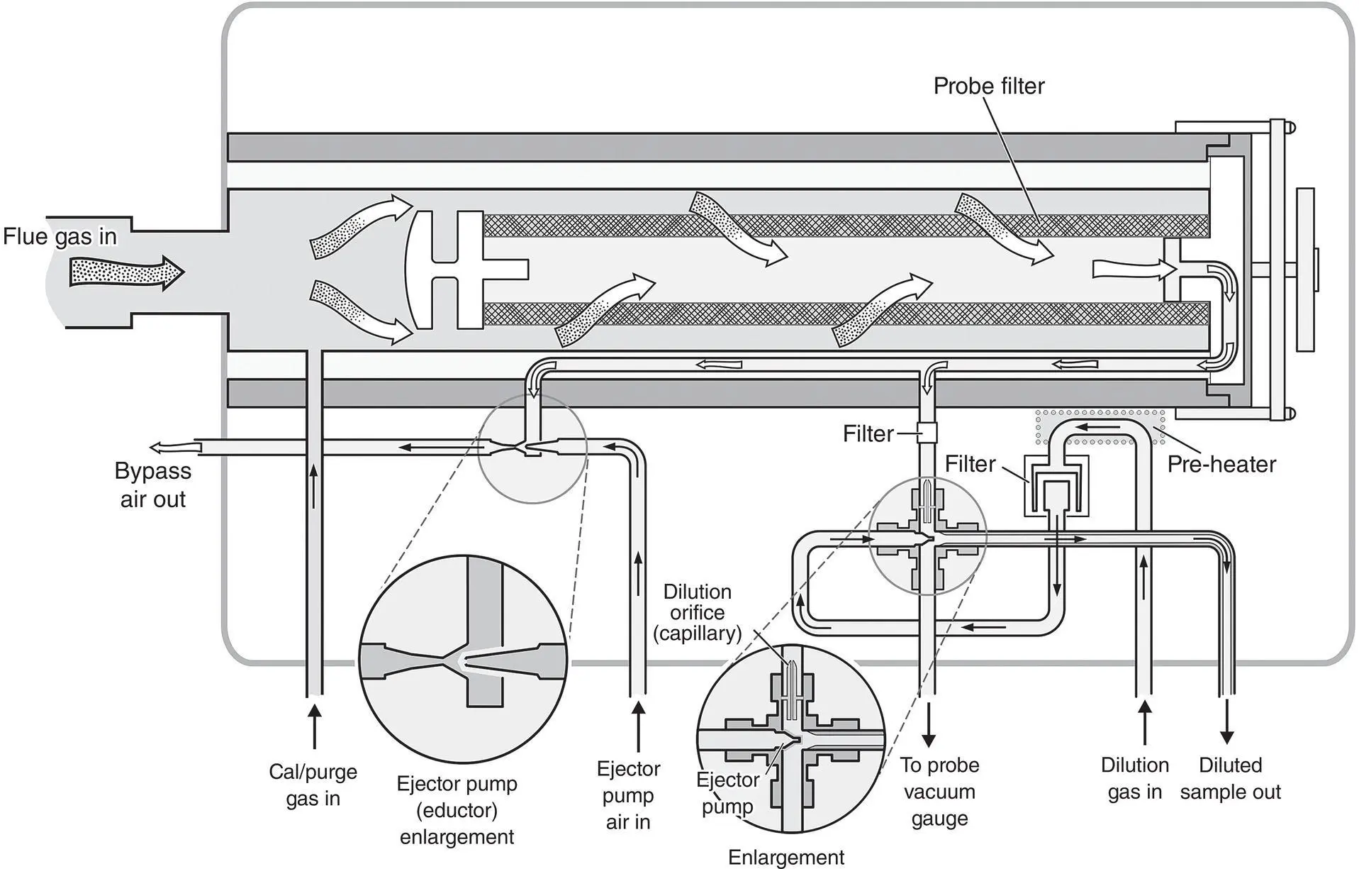
Figure 3‐22 External dilution system with cross‐piece dilution unit.
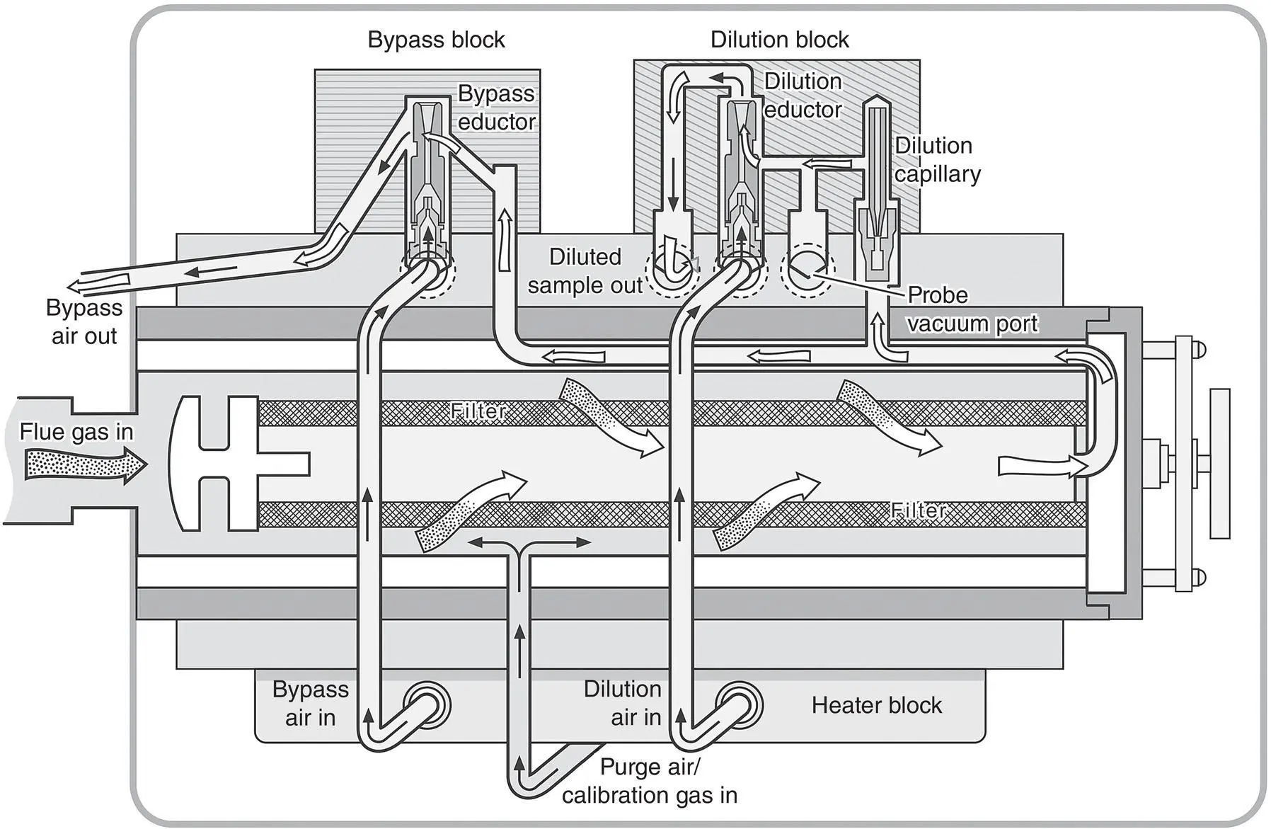
Figure 3‐23 Dilution system with modular block dilution unit.
In the daily calibration verification of the CEM system, the calibration gas is sent through the calibration/purge gas line (shown in Figure 3‐23at the bottom of the assembly) at a flow rate sufficient to flood the annulus outside of the filter, expelling the flue gas. The calibration gas is then extracted by the CEM system similarly to the sample gas, being conditioned in the same manner as the sample gas.
The STI Probe.
The first external dilution probe was developed to address plugging of dilution orifices by water droplets in the EPM probe by Sampling Technology, Inc. (STI) and is available from STI and Thermo Fisher Scientific ( Figure 3‐24). This external dilution system, made of Torlon, is shown in Figure 3‐24(Fischer 1993). It again uses an ejector pump to extract the sample from the stack and has been popular in pulp and paper industry applications, particularly after wet scrubbers. The flue gas sample extracted at low flow rates is first filtered by a tubular filter, where particulate matter and aerosols not dropping out in the probe are collected. A quartz capillary serves as the critical orifice, which controls the sample gas flow rate. The sample gas combines with the ejector pump air as in other dilution systems described.
As mentioned previously, one advantage of an external dilution system is that an undiluted sample can be first sent to an O 2analyzer before it proceeds to the dilution system. This provides an alternative to using a CO 2analyzer for the diluent monitor. A separate sample line can be installed after the probe filter, but before the dilution orifice, to draw an undiluted sample. This sample can then be conditioned to remove water vapor and analyzed with an oxygen sensor.
An alternative approach to external dilution systems is to transport the gas from the stack in the traditional manner of a source‐level extractive system and to dilute the gas in the CEM shelter. This does provide for rapid gas transport, but a heated sample line must be used. This approach loses one of the principal advantages of dilution systems – their ability to deliver the sample to the analyzers with unheated sample line.
Enhancing the Operation of Dilution Systems
In today's applications for CEM systems, new demands have been made for dilution systems and CEM systems in general. For example, in the acid rain program, relative accuracy specifications became more stringent at 10%, daily calibration error (drift) is limited to 2.5% of span, and a 5% linearity criterion has been established. Although relative accuracy specifications are not difficult to meet, it is found that a clear understanding of the operating characteristics of dilution systems is necessary to achieve the optimum performance necessary for meeting the drift and linearity test specifications.
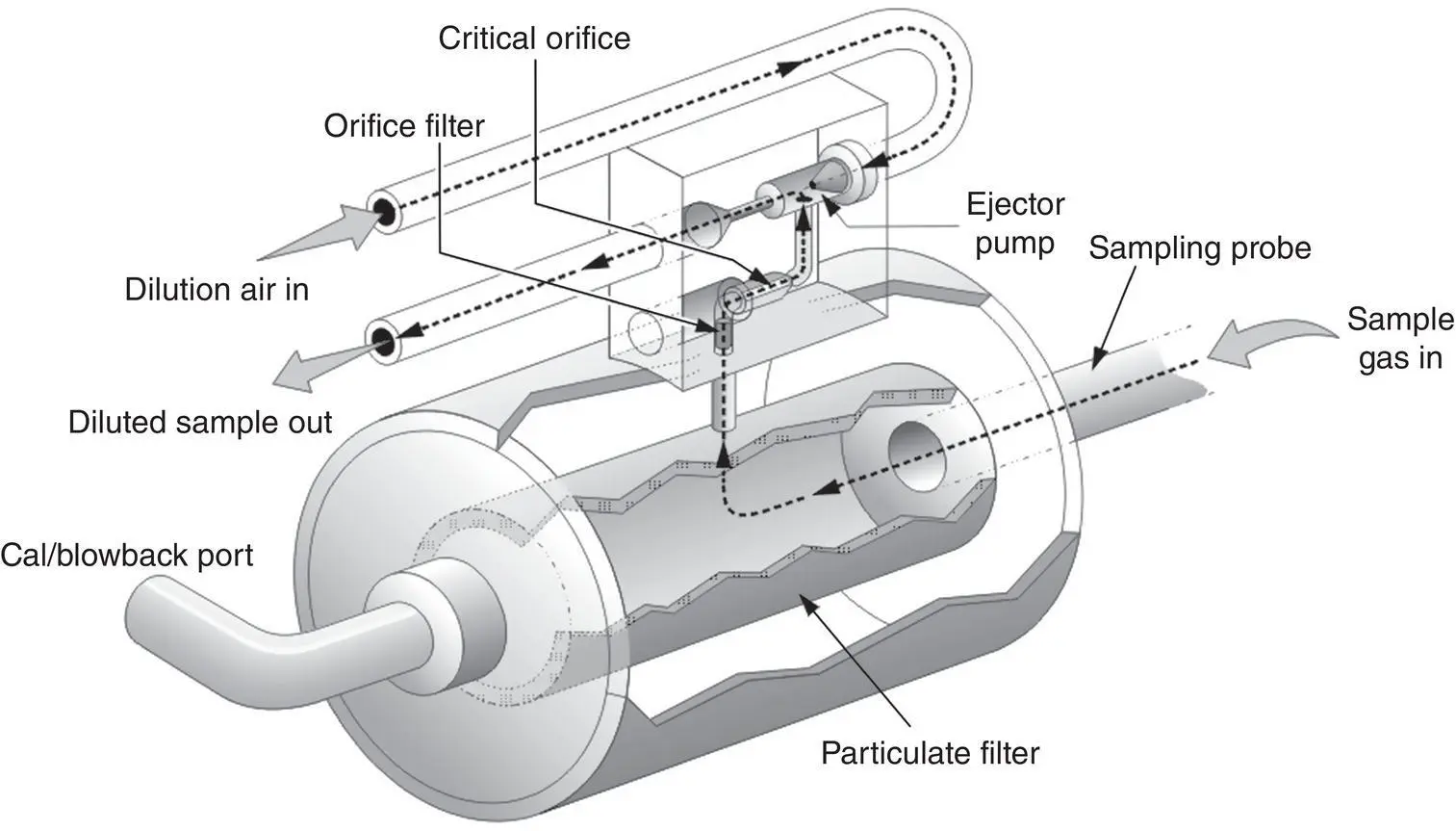
Figure 3‐24 STI external dilution system design.
In dilution systems, the flue gas concentration is calculated from the dilution ratio as follows:
(3‐3) 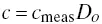
where
c = the calculated source‐level concentration of the gas (ppm)
cmeas = the analyzer response (ppm) to the diluted sample
Do = the dilution ratio at the time of calibration
This equation assumes that the dilution ratio remains the same while the reading c measis obtained as when the dilution system was calibrated initially. This is not always the case. If the absolute pressure changes from P oto P , the stack temperature changes from T oto T , or the molecular weight of the sampled gas changes from M oto M , the dilution ratio will change also. Pressure, temperature, and molecular weight all affect gas density, which affects the sonic flow of the gas through the orifice. A change in gas density will therefore affect the dilution ratio.
Problems arise when the original conditions at which the dilution system was first calibrated change for any subsequent measurements. Figure 3‐25illustrates the principal factors that may cause a change in the dilution ratio.Consider the following scenarios illustrated in the figure:
Figure 3‐25 Principal factors causing changes in dilution systems.
Scenario 1 A dilution system is calibrated initially when the total stack pressure PT = Pbar + ps, the unit is on, the flue gas temperature = To, and the calibration gas has an average molecular weight = Mo. Typically, any variation from the nominal dilution ratio is adjusted out by setting the analyzers to the certified calibration gas concentration during calibration.
Scenario 2 A dilution system is calibrated at a stack absolute pressure of Po. A weather front moves in and the atmospheric pressure is reduced. A calibration check will indicate an upward drift in reading.
Scenario 3 A dilution system is installed on a cycling unit and is calibrated when the unit is off, at a temperature To. After the unit is turned on and the stack temperature increases, a calibration check will indicate a downward drift in reading.
Scenario 4 A dilution system is calibrated with an SO2 in N2 calibration gas. An auditor conducts a linearity test using a gas mixture containing SO2 and 20% CO2. The test gives a reading lower than expected.
Читать дальшеИнтервал:
Закладка:
Похожие книги на «Continuous Emission Monitoring»
Представляем Вашему вниманию похожие книги на «Continuous Emission Monitoring» списком для выбора. Мы отобрали схожую по названию и смыслу литературу в надежде предоставить читателям больше вариантов отыскать новые, интересные, ещё непрочитанные произведения.


Обсуждение, отзывы о книге «Continuous Emission Monitoring» и просто собственные мнения читателей. Оставьте ваши комментарии, напишите, что Вы думаете о произведении, его смысле или главных героях. Укажите что конкретно понравилось, а что нет, и почему Вы так считаете.