James A. Jahnke - Continuous Emission Monitoring
Здесь есть возможность читать онлайн «James A. Jahnke - Continuous Emission Monitoring» — ознакомительный отрывок электронной книги совершенно бесплатно, а после прочтения отрывка купить полную версию. В некоторых случаях можно слушать аудио, скачать через торрент в формате fb2 и присутствует краткое содержание. Жанр: unrecognised, на английском языке. Описание произведения, (предисловие) а так же отзывы посетителей доступны на портале библиотеки ЛибКат.
- Название:Continuous Emission Monitoring
- Автор:
- Жанр:
- Год:неизвестен
- ISBN:нет данных
- Рейтинг книги:4 / 5. Голосов: 1
-
Избранное:Добавить в избранное
- Отзывы:
-
Ваша оценка:
Continuous Emission Monitoring: краткое содержание, описание и аннотация
Предлагаем к чтению аннотацию, описание, краткое содержание или предисловие (зависит от того, что написал сам автор книги «Continuous Emission Monitoring»). Если вы не нашли необходимую информацию о книге — напишите в комментариях, мы постараемся отыскать её.
The new edition of the only single-volume reference on both the regulatory and technical aspects of U.S. and international continuous emission monitoring (CEM) systems Continuous Emission Monitoring
Continuous Emission Monitoring:
Continuous Emission Monitoring, Third Edition
Continuous Emission Monitoring — читать онлайн ознакомительный отрывок
Ниже представлен текст книги, разбитый по страницам. Система сохранения места последней прочитанной страницы, позволяет с удобством читать онлайн бесплатно книгу «Continuous Emission Monitoring», без необходимости каждый раз заново искать на чём Вы остановились. Поставьте закладку, и сможете в любой момент перейти на страницу, на которой закончили чтение.
Интервал:
Закладка:
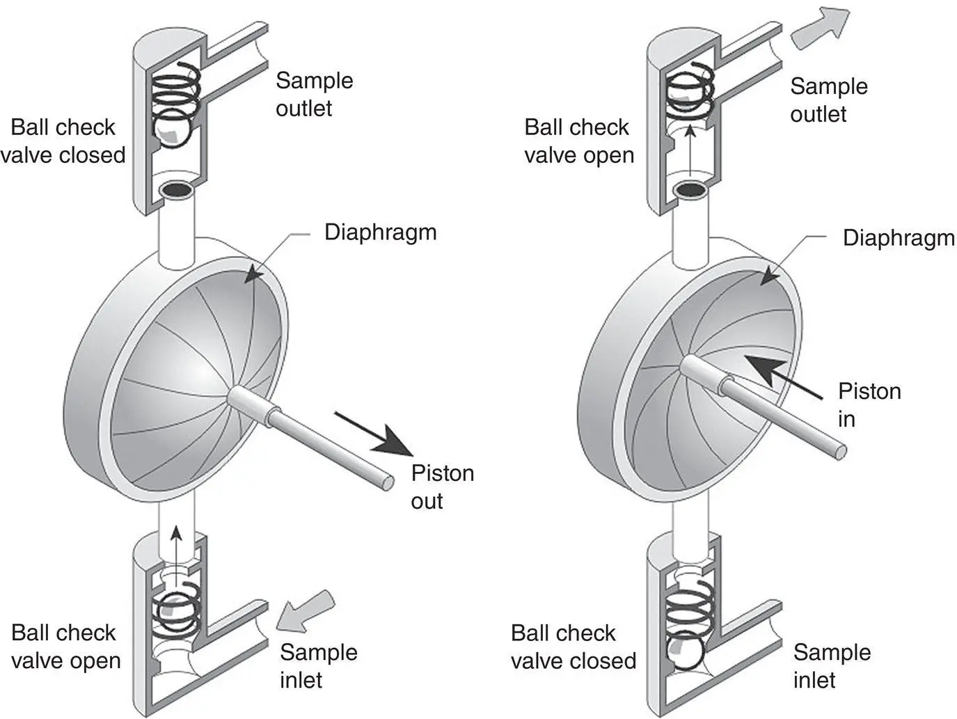
Figure 3‐13 A diaphragm pump.
Diaphragm pumps can be used before the sample gas conditioning system and can even be operated hot. However, particulate matter and condensed acid can weaken the pump head by particle abrasion or chemical attack. Unless the gas is properly filtered and the pump head adequately heated, it is better to locate the pump after the conditioning system. Eventually, the continual, rapid flexing action of the pump will cause the diaphragm to split or tear.
The flow rate of a diaphragm pump can be controlled by placing a throttle valve in the line on the discharge side of the pump or by installing a by‐pass line and valve from the suction side to the discharge side. If the pump is operating at less than its full capacity, controlling flow with the throttle valve will cause the pump to work against a high discharge pressure and pump life will be reduced. For this reason, it is better to control the flow using a bypass valve.
The ejector pump (also called an eductor or air aspirator) takes advantage of the Bernoulli effect to draw a vacuum through a sampling system ( Figure 3‐14). In the Bernoulli effect, the moving jet of air reduces the air pressure normal to its flow. This is a common effect that is familiar in venturi flowmeters and jet carburetors. This reduced pressure pulls the sample gas through the sample line; if the jet velocity increases, the vacuum increases. Typically, the filtered plant air or compressed cylinder gas is used for the high‐velocity gas stream. The ejector pump is simple in its design and can be incorporated as part of an inertial filter probe system as shown in Figure 3‐7. Here, the pump draws in the sample through an inertial filter that would be installed in a heated cabinet located outside the stack. Another pump, usually a diaphragm pump, is used to pull the filtered sample to the analyzer. In the ejector pumps applied where the sample gas is not filtered, particulate matter can build up and dry out in the annular space of the pump. In such cases, it may be necessary to use steam instead of compressed air to provide the motive force for the pump action.
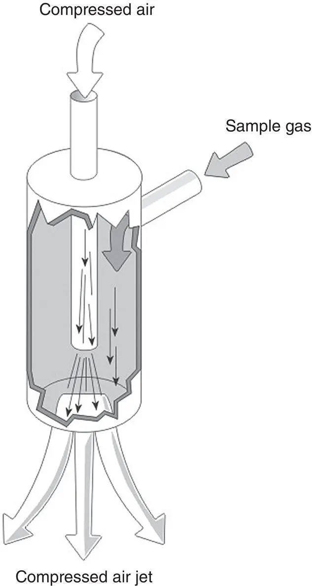
Figure 3‐14 The ejector pump or eductor.
Fine Filters
The coarse filter is used to remove larger particles from the sample gas. Because the majority of gas analyzers require almost complete removal of particles larger than 0.5 μm, additional filtration is necessary. This is accomplished by incorporating a fine filter before the analyzer inlet. The location of the fine filter is an important consideration in the CEM system design and is dependent upon the susceptibility of the other system components to the effects of fine particles. There are two types of fine filters: (i) surface filters and (ii) depth filters.
A surface filter can be simply a filter paper that excludes particles of a certain size. The filter material is porous to the moving gas, but the pores are of such a size that they prevent penetration of fine particulate matter. A filter cake can also build up on the filter, further reducing the size of particles passing into the gas stream. Because of the filter cake and developed electrostatic charges, surface filters can remove particles smaller than the actual filter pore size.
Depth filters collect particles within the bulk of a filter material. The filter may consist of loosely packed fibers of quartz wool or of filter material wrapped to a depth sufficient to remove fine particles. Such filters work particularly well for dry solids and moist gas streams containing aerosols. A depth filter can also be used as a probe filter, a technique that is used in some systems.
Assembling a Cool/Dry Extractive System
Designing and assembling a cool/dry extractive system is a relatively straightforward process. System components, such as probes, chillers, filters, and pumps are available from many suppliers and can be purchased individually to incorporate into a system design. Alternatively, several suppliers provide modular conditioning systems and modular calibration gas distribution systems that simplify the assembly. An example of a plumbing system for a cool‐dry extractive system is shown in Figure 3‐15.
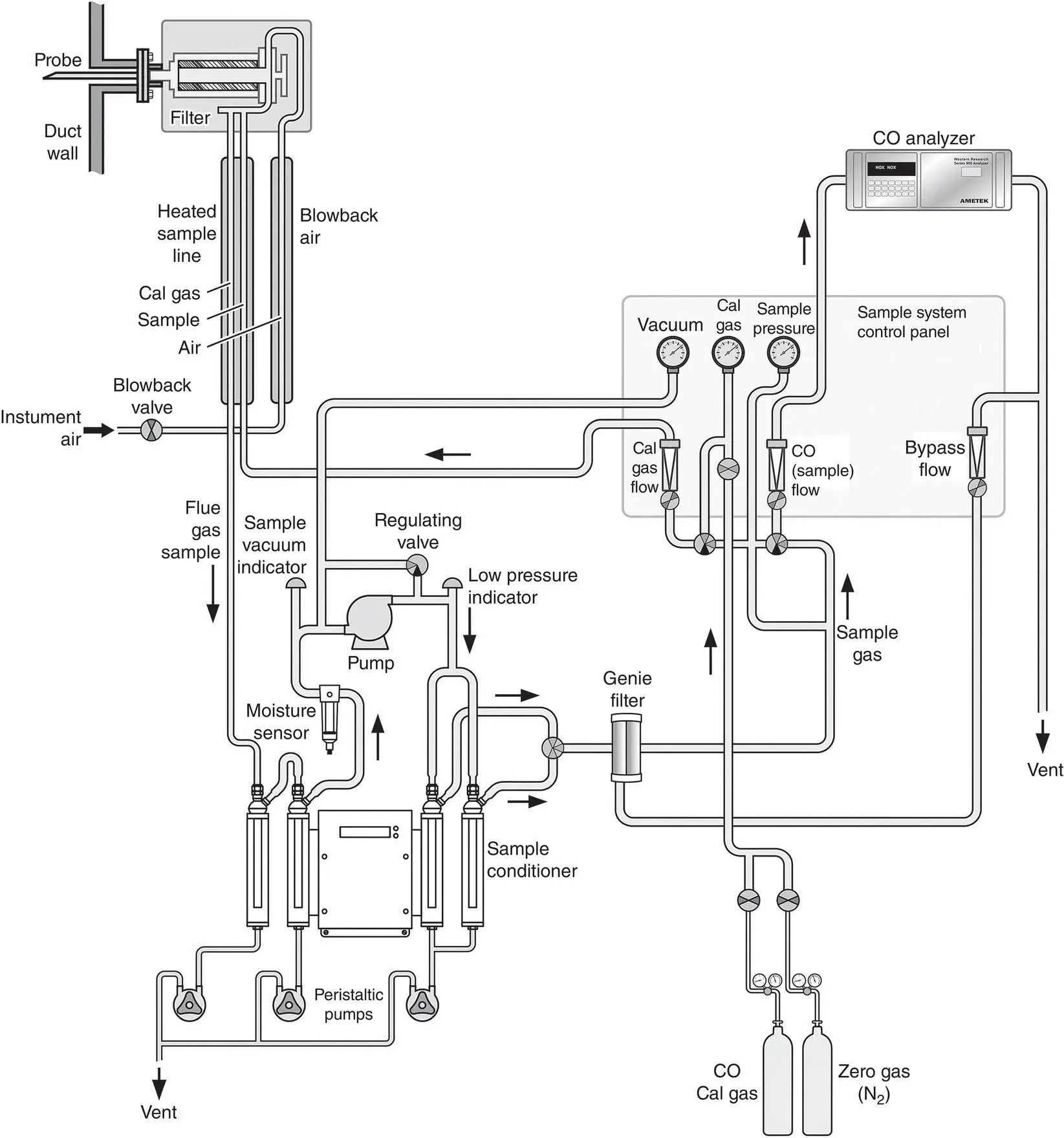
Figure 3‐15 A cool/dry extractive system for monitoring CO.
The example shows a simple sample probe (stinger) attached to a heated, coarse filter external to the stack. Instrument air is provided for particulate blowback from the filter. Two sets of impingers, cooled with a Peltier cooler, condense moisture from the flue gas sample. The condensed water vapor is removed from the system using peristaltic pumps. A water break‐through detector is incorporated into the line after the first set of impingers and before the sampling pump. The sampling pump transports the dry sample gas to the analyzer after passing through a fine filter. The sample system control panel monitors vacuum, pressures, and flow rates at various points in the system. The control panel may provide for either manual or automatic control of the gas distribution although today most systems are automatically controlled. The system illustrated shows only one gas analyzer, but can be expanded to monitor multiple gases.
Although assembling such components to construct a CEM system may appear straightforward, it is important that the system design be appropriate for the application. If emissions need to be reported on a mass rate basis (kg/hr), if the pollutant is partially soluble in water and the emission limit is 10 ppm instead of 200 ppm, a hot/wet or dilution extractive system might be more appropriate. Other factors such as flue gas temperature, moisture content, and particulate concentration must also be considered in the system design. High temperatures and/or high levels of particulate matter or sticky particulate matter may limit the choice of probes and filters. Similarly, high moisture levels or the presence of acid gases may limit the choice of sample coolers. For challenging applications, experience in system design is important. It is this experience that distinguishes CEM system integrators from each other. It also may make a difference in the success of the system in passing its initial certification test and its success in operating continually without excessive maintenance demands.
Not shown in the diagram are the electrical and communication systems necessary for system control and data utilization. These aspects of the CEM system are the most difficult to accommodate into a CEM system installation because they must be integrated into existing plant networks. Most CEM systems do not stand alone, but are often used for control and optimization of the monitored operating unit. Alarms, emission values, calibration results, and real‐time as well as summary data are typically routed to the plant distributed control system, or separately to the environmental manager or corporate office. All of this takes coordination and collaboration with plant personnel and contractors to assure that CEM system electrical connections and communications are properly integrated into the existing systems of the plant. Compared to these challenges, assembly of monitoring system hardware is the simplest part of the installation program.
Читать дальшеИнтервал:
Закладка:
Похожие книги на «Continuous Emission Monitoring»
Представляем Вашему вниманию похожие книги на «Continuous Emission Monitoring» списком для выбора. Мы отобрали схожую по названию и смыслу литературу в надежде предоставить читателям больше вариантов отыскать новые, интересные, ещё непрочитанные произведения.


Обсуждение, отзывы о книге «Continuous Emission Monitoring» и просто собственные мнения читателей. Оставьте ваши комментарии, напишите, что Вы думаете о произведении, его смысле или главных героях. Укажите что конкретно понравилось, а что нет, и почему Вы так считаете.