James A. Jahnke - Continuous Emission Monitoring
Здесь есть возможность читать онлайн «James A. Jahnke - Continuous Emission Monitoring» — ознакомительный отрывок электронной книги совершенно бесплатно, а после прочтения отрывка купить полную версию. В некоторых случаях можно слушать аудио, скачать через торрент в формате fb2 и присутствует краткое содержание. Жанр: unrecognised, на английском языке. Описание произведения, (предисловие) а так же отзывы посетителей доступны на портале библиотеки ЛибКат.
- Название:Continuous Emission Monitoring
- Автор:
- Жанр:
- Год:неизвестен
- ISBN:нет данных
- Рейтинг книги:4 / 5. Голосов: 1
-
Избранное:Добавить в избранное
- Отзывы:
-
Ваша оценка:
Continuous Emission Monitoring: краткое содержание, описание и аннотация
Предлагаем к чтению аннотацию, описание, краткое содержание или предисловие (зависит от того, что написал сам автор книги «Continuous Emission Monitoring»). Если вы не нашли необходимую информацию о книге — напишите в комментариях, мы постараемся отыскать её.
The new edition of the only single-volume reference on both the regulatory and technical aspects of U.S. and international continuous emission monitoring (CEM) systems Continuous Emission Monitoring
Continuous Emission Monitoring:
Continuous Emission Monitoring, Third Edition
Continuous Emission Monitoring — читать онлайн ознакомительный отрывок
Ниже представлен текст книги, разбитый по страницам. Система сохранения места последней прочитанной страницы, позволяет с удобством читать онлайн бесплатно книгу «Continuous Emission Monitoring», без необходимости каждый раз заново искать на чём Вы остановились. Поставьте закладку, и сможете в любой момент перейти на страницу, на которой закончили чтение.
Интервал:
Закладка:
One solution to minimizing adsorption of volatile organic compounds has been the development of glass‐coated flexible stainless‐steel tubing (Gerhab and Schuyler 1996). This combination of fused silica and stainless steel can be heated to desorb gases from the tubing surface, if necessary. The company SilcoTek, (formerly, Restek) located in Bellefonte, PA, is the principal supplier of coating services for tubing, parts, fittings, chemical reactors, and process industry components. Proprietary materials such as SilcoNert ®, Dursan ®, and others are deposited by chemical vapor deposition to a depth of typically 2 μm (SilcoTek 2017).
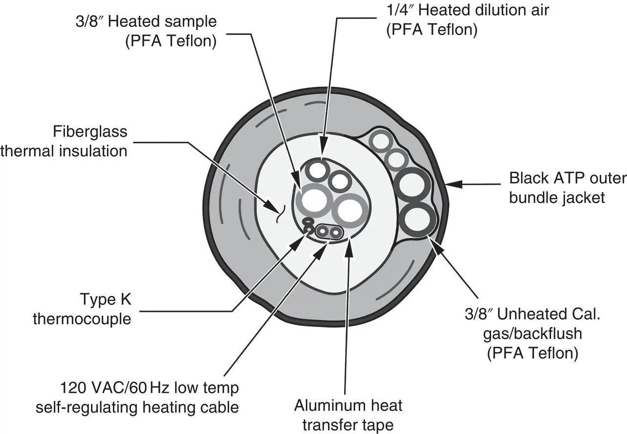
Figure 3‐9 Umbilical line cross section for a dilution extractive system.
Chemical attack and wall adsorption effects can be a problem when sampling reactive gases. For example, Marshak (2015, 2019) and Hoard et al. (2014) have examined the problem of NH 3retention in detail, using an FTIR spectrometer. At a flow rate of 3 l/min, they found that the time it takes for an NH 3calibration gas value to stabilize at the analyzer can be significant, particularly when using untreated stainless‐steel sample lines. They also found that NH 3adsorption of the sample system walls was dependent upon line temperature, flow rates, and the material. However, line length and diameter were not found to have a statistically significant effect. It was also found that PFA and SilcoNert® stainless steel lines work well for NH 3with a flow rate of > 5 l/min, where 10–15 l/min may be preferable. Also, humidification of the sample and higher line temperatures reduced adsorption. SilcoNert ®stainless steel was found to be the best for sample probes, and filters composed of borosilicate glass were found to be better.
Umbilicals are usually custom‐made and can contribute significantly to the expense of an extractive system. Umbilicals are usually priced per running foot and a total fixed price is generally not quoted by CEM system vendors unless the exact length is provided in a CEM system bid specification. Heated umbilicals are generally less than 250 ft in length, although longer lines can be installed if sufficient attention is paid to their construction. Freeze‐protect lines for dilution extractive mercury monitoring systems have worked well even at a length of 1000 ft; however, costs can be significant if, and when, they need to be replaced.
The time that it will take for gas to flow through a sample line will depend on the sample tube diameter, its length, and the flow rate. This lag can be roughly calculated from the expression (McNulty et al. 1974)
(3‐1) 
where
t = the lag time (in minutes)
V = sample line volume (in liters)
Qsl = volumetric flow rate of gas through the line (liters per minute)
This expression is oversimplified since it assumes that there are no frictional wall effects restricting the flow. It shows, however, that if the sample line length is increased, the lag time will increase as the sample line volume increases. Typically, for a flow rate of 1 standard liter per minute (l/min), the lag time for a 100‐ft section of a 0.25‐in. internal diameter tube at a pressure drop of 152 mm Hg is only 30 s.
Hot spots should be avoided when installing a heated umbilical. Hot spots can be caused by the loss of temperature control through communication or temperature sensor failures or damages due to flexing problems. Hot spots can also occur if the bundle is clamped too tightly to a support, if the tubing makes contact with itself, or if multiple heated bundles are tied together, or if account is not taken for the temperature gradient between the inside and outside of a CEM shelter, in which case multiple heated zones may be necessary. The line should have a continuous downward slope from the probe to the conditioning system (5° is recommended) in case of condensation within the line, avoiding sags where condensate might collect, yet allowing for sufficient freedom for strain relief to allow for thermal expansion and contraction, especially when starting up or shutting down a unit. In the case of short circuits, damages may be minimized by incorporating ground fault circuit interrupter (GFCI) circuit breakers, tripping at 20 MA, into the system (Robinson 2010).
Condensation by water, acid, and other gases in cooler “pockets” can increase system corrosion or line plugging if fine particles are not adequately filtered at the probe. Sample lines can also become contaminated with reacted materials, which are difficult to remove. Plugs of particulate matter are difficult to remove in the heated sample line, and if a heater wire breaks or burns out, it is often difficult to find the break. On occasion, entire umbilicals will need to be replaced when these problems cannot be resolved (Bembe 2019).
Proper design and installation of the umbilical is important for its operation. This is not the area where costs can be cut. The use of inferior materials, installation by inexperienced personnel, and ad hoc supporting and fastening methods have led to numerous umbilical failures in the past (Robinson 2010). It is highly recommended that the umbilical manufacturer either supervise or be on‐site during installation. Lastly, the umbilical should be routed to avoid the possibility of damages by facility vehicles, cranes, forklifts, or other plant equipment.
Calibration Gas System and Cylinder Gas Pressure Regulators
A calibration gas delivery system is a component of any extractive sampling systems designed for meeting regulatory requirements in the United States and Canada. In North America, CEM systems are required to be calibrated against NIST‐certified calibration gases meeting established traceability protocols (Schakenbach et al. 2002; U.S. EPA 2012). Monitoring system calibration is required to be verified daily, and monitoring system linearity must also be audited quarterly using “protocol” gases injected as close to the probe as possible, passing through all components of the extractive system to the analyzers.
The calibration gas system typically extends from the calibration gas cylinders, through a gas pressure regulator, to an automated gas injection control system, through a dedicated line in the umbilical, and on to the injection port ( Figures 3‐15and 3‐21). The gas returns through the sample line to the analyzer(s). The calibration gas line may be either in the umbilical (which may be heated or unheated) or separated from the main umbilical in an unheated line. Components typically in contact with the calibration gas will be the calibration gas cylinder pressure regulator, calibration gas delivery line, the sample gas probe, the sample line, and the internal surfaces of the analyzer sample cell.
The use of cylinder gas pressure regulators is often taken for granted and can be a factor in the delivery of reactive calibration gases. Reactive gases such as HCl and NH 3can stick to surfaces in the regulator as well as to the calibration gas delivery line, where the gas adsorption is dependent upon the materials of construction, flow rate, temperature, and the prior status of the delivery system. Moisture or other contamination in the regulator can have effects that may be difficult to uncover if proper precautions are not taken. Water in the air can condense in a regulator and regulators used for other purposes may have an unknown history that could lead to losses of the gas. Similar to calibration gas lines, regulators treated with SilcoNert ®reduce surface absorption.
Читать дальшеИнтервал:
Закладка:
Похожие книги на «Continuous Emission Monitoring»
Представляем Вашему вниманию похожие книги на «Continuous Emission Monitoring» списком для выбора. Мы отобрали схожую по названию и смыслу литературу в надежде предоставить читателям больше вариантов отыскать новые, интересные, ещё непрочитанные произведения.


Обсуждение, отзывы о книге «Continuous Emission Monitoring» и просто собственные мнения читателей. Оставьте ваши комментарии, напишите, что Вы думаете о произведении, его смысле или главных героях. Укажите что конкретно понравилось, а что нет, и почему Вы так считаете.