James A. Jahnke - Continuous Emission Monitoring
Здесь есть возможность читать онлайн «James A. Jahnke - Continuous Emission Monitoring» — ознакомительный отрывок электронной книги совершенно бесплатно, а после прочтения отрывка купить полную версию. В некоторых случаях можно слушать аудио, скачать через торрент в формате fb2 и присутствует краткое содержание. Жанр: unrecognised, на английском языке. Описание произведения, (предисловие) а так же отзывы посетителей доступны на портале библиотеки ЛибКат.
- Название:Continuous Emission Monitoring
- Автор:
- Жанр:
- Год:неизвестен
- ISBN:нет данных
- Рейтинг книги:4 / 5. Голосов: 1
-
Избранное:Добавить в избранное
- Отзывы:
-
Ваша оценка:
Continuous Emission Monitoring: краткое содержание, описание и аннотация
Предлагаем к чтению аннотацию, описание, краткое содержание или предисловие (зависит от того, что написал сам автор книги «Continuous Emission Monitoring»). Если вы не нашли необходимую информацию о книге — напишите в комментариях, мы постараемся отыскать её.
The new edition of the only single-volume reference on both the regulatory and technical aspects of U.S. and international continuous emission monitoring (CEM) systems Continuous Emission Monitoring
Continuous Emission Monitoring:
Continuous Emission Monitoring, Third Edition
Continuous Emission Monitoring — читать онлайн ознакомительный отрывок
Ниже представлен текст книги, разбитый по страницам. Система сохранения места последней прочитанной страницы, позволяет с удобством читать онлайн бесплатно книгу «Continuous Emission Monitoring», без необходимости каждый раз заново искать на чём Вы остановились. Поставьте закладку, и сможете в любой момент перейти на страницу, на которой закончили чтение.
Интервал:
Закладка:
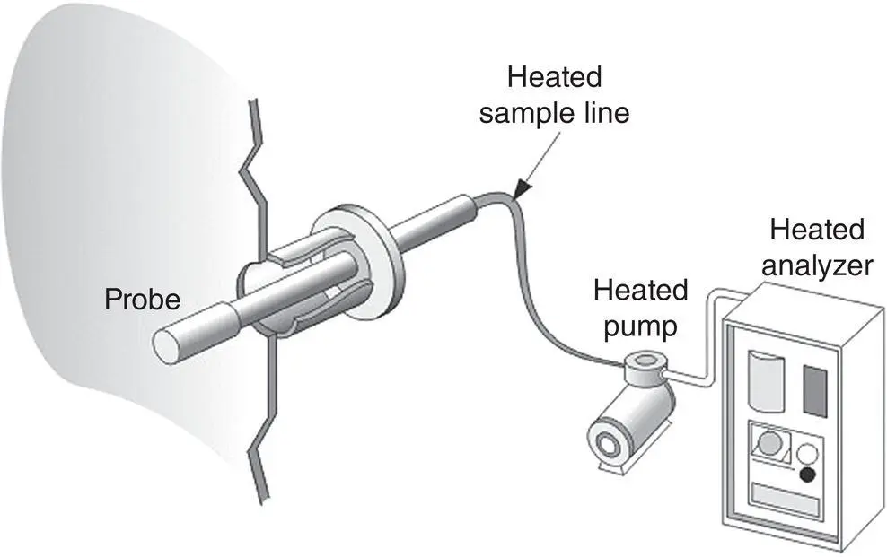
Figure 3‐1 A hot/wet CEM system without sample conditioning.
Hot/wet systems are often used in association with ultraviolet analyzers designed for the measurement of SO 2and NO x. When a wet‐basis pollutant measurement is obtained in conjunction with a volumetric flow measurement, the pollutant mass concentration can be obtained directly from the product of the two measurements (pollutant mass rate = concentration(wet) × volumetric flow rate (wet)). In contrast, when a cool/dry concentration measurement is obtained, a knowledge of the flue gas moisture content is necessary to calculate the pollutant mass rate. This adds both complexity and possible errors to such a monitoring system.
Hot/wet systems are also useful for measuring water‐soluble gases such as HCl, NH 3, and certain volatile organic compounds. The chiller in a cool/dry extractive system will remove these gases either in part or entirely, so either a hot/wet system or dilution extractive system would be necessary to deliver a representative sample to the analyzer. A hot extractive system and a hot analyzer can also minimize the adsorption of gases on the extractive system surfaces. Chemical reactions such as NO to NO 2conversion (Sneek 1997) and ammonium sulfate (White 1995) or ammonium chloride (Peeler et al. 1997) formation can be minimized by using higher‐temperature extractive systems.
Cool/Dry Systems with Conditioning
In a more widely applied extractive system design, the gas is conditioned before it enters the analyzer. The gas temperature is reduced to ambient temperature and moisture is removed, so that the sample is both cool and relatively dry. The conditioning may be conducted either at the probe location ( Figure 3‐2) or at the analyzer shelter ( Figure 3‐3). Conditioning at the probe location offers the advantage of using unheated sampling line; however, preventive maintenance of the conditioning system at the probe may be inconvenient. Conditioning at the shelter or CEM room enables the CEM system operator to check the system performance conveniently. However, the necessary heat‐traced lines must be maintained at a proper temperature over their entire length.
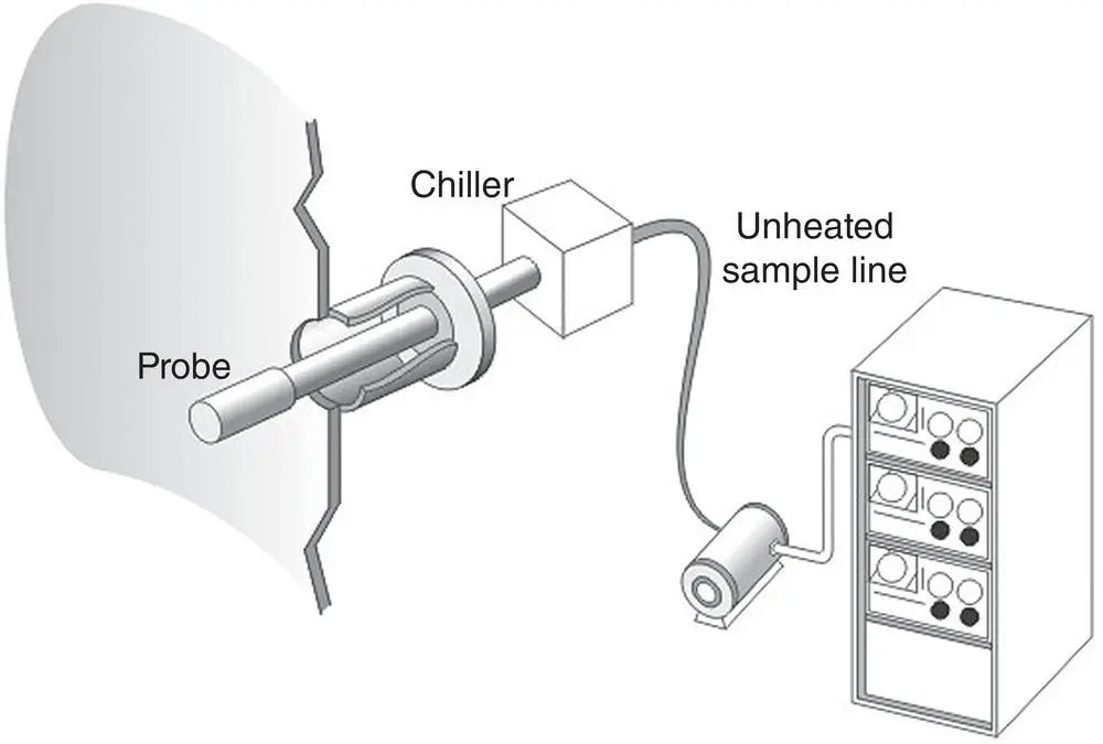
Figure 3‐2 A cool/dry CEM system with conditioning at the probe.
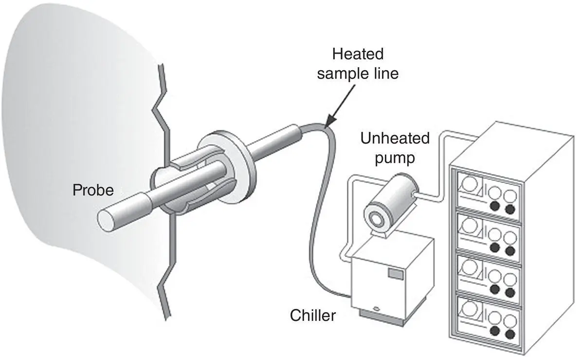
Figure 3‐3 A cool/dry CEM system with conditioning at the CEM system shelter.
Extractive systems that condition the flue gas allow greater flexibility in the choice of analyzers and are commonly used when emission calculations are performed on a dry basis or when monitoring a number of different gases is required. Although this type of system is not as sophisticated as some others, it is flexible enough to accommodate engineering changes when application problems arise. In problem applications, the system components can be readily modified or replaced so that the system can meet performance specifications.
A source‐level extractive system is made up of a set of basic components: probe, sample line, filters, moisture removal system, and pump. Because the operation of an extractive system is dependent on the design and quality of each component, as well as on their arrangement in the system, it is necessary to review these characteristics.
Sample Probes
A sample probe (sometimes called a “stinger”) can be made by merely inserting an open metal tube into the stack or duct, or multipoint probes may be used to sample from several locations when the flue gas is stratified (Shahin 2016). This may be adequate in sampling situations where no particulate matter is present. However, flue gases free of particulate matter do not often occur in those sources that are subject to CEM regulation. An open tube can be easily plugged when particulate matter is present, especially if the flue gas has high moisture content. Also, water may condense and combine with the particulate matter to produce an agglomerated material that can plug the probe more readily. To minimize such problems, a filter can be placed at the end of the probe ( Figure 3‐4a–c).
Filters made of sintered stainless steel and porous ceramic materials are commonly used to prevent particles from entering the sample tube. Sintered metal is made by compressing micrometer‐sized metal granules under high pressure and elevated temperatures. The metal fuses and acquires porosity depending on the compression pressure. Sintered stainless steel filters that are capable of filtering out particles of 5 to 50 μm have been used as probe filters. Some systems use filters that exclude particles greater than 1–2 μm in size, but the finer the filter, the more difficult it will be to draw the sample gas through the filter, and pump capacity will need to be increased.
Sintered filters or ceramic filters can become plugged by the particles impacting on and penetrating into the porous material. To minimize plugging, a baffle plate can be attached to the filter to deflect particles from the filter surface ( Figure 3‐4b). Particles will then follow streamlines formed around the plate, whereas pollutant gases will still diffuse into the probe. Another way to minimize plugging is to attach a cylindrical sheath around the filter ( Figure 3‐4c). Gas will still diffuse into the annular space between the filter and baffle, but most particles will not be able to make the 90° change in the direction to enter the space. If the end of such a sheath is partially closed off with a porous plate to provide for gas diffusion, the external filter probe can undergo a probe calibration check. Calibration gas can be injected into the sheath to flood out the stack gas during the calibration intervals.
In the probe designs shown in Figure 3‐4a–c, the coarse particulate filter is attached at the end of the probe. In another probe design, this filter is mounted externally, in a housing mounted outside the stack ( Figure 3‐5).
In filter assemblies mounted outside of the stack, a heater either can be fitted into the assembly or placed around the outside of the filter holder. This allows the hot flue gas sample to remain hot as it is drawn through the filter and passed through to the heated sample line and the remainder of the conditioning system. The principal advantage of this configuration is that the coarse filter can be easily unclamped and inspected. The entire probe assembly does not need to be unbolted and removed from the stack to replace the filter, and if the probe becomes plugged with particulate matter, the plug can be pushed out with a rod. Also, if the probe is mounted at an angle ( Figure 3‐5), water or acid condensed in the probe can roll back into the stack.
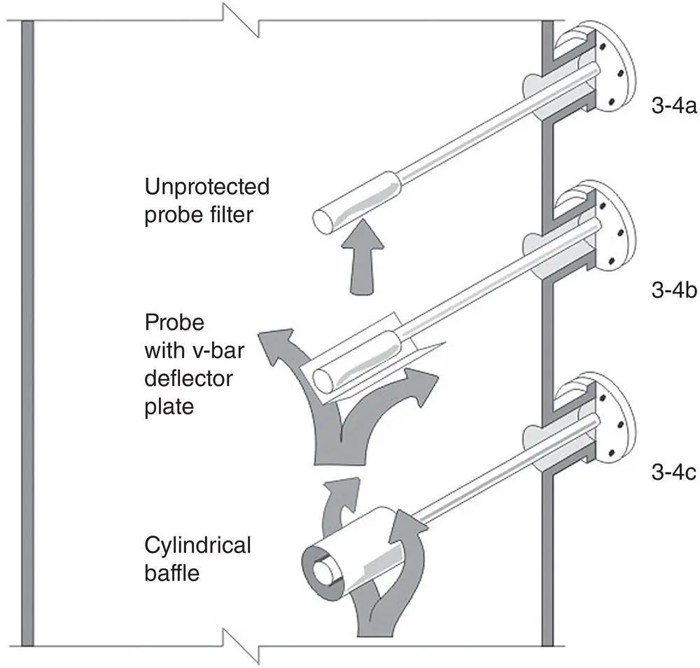
Figure 3‐4 (a) A simple probe filter. (b) Sintered filter with a baffle plate deflector. (c) Sintered filter with a deflector sheath.
Extractive systems designed with external filter housings can readily undergo a calibration verification at the filter housing. Calibration gases can be injected into the annular space between the filter and the housing to provide a check of system integrity from the filter back to the analyzer. This is difficult to do with in‐stack filters because the filter is constantly subject to the flue gas flow and excessive amounts of calibration gas may be needed to continually flood the area around the filter during a calibration verification.
Читать дальшеИнтервал:
Закладка:
Похожие книги на «Continuous Emission Monitoring»
Представляем Вашему вниманию похожие книги на «Continuous Emission Monitoring» списком для выбора. Мы отобрали схожую по названию и смыслу литературу в надежде предоставить читателям больше вариантов отыскать новые, интересные, ещё непрочитанные произведения.


Обсуждение, отзывы о книге «Continuous Emission Monitoring» и просто собственные мнения читателей. Оставьте ваши комментарии, напишите, что Вы думаете о произведении, его смысле или главных героях. Укажите что конкретно понравилось, а что нет, и почему Вы так считаете.