James A. Jahnke - Continuous Emission Monitoring
Здесь есть возможность читать онлайн «James A. Jahnke - Continuous Emission Monitoring» — ознакомительный отрывок электронной книги совершенно бесплатно, а после прочтения отрывка купить полную версию. В некоторых случаях можно слушать аудио, скачать через торрент в формате fb2 и присутствует краткое содержание. Жанр: unrecognised, на английском языке. Описание произведения, (предисловие) а так же отзывы посетителей доступны на портале библиотеки ЛибКат.
- Название:Continuous Emission Monitoring
- Автор:
- Жанр:
- Год:неизвестен
- ISBN:нет данных
- Рейтинг книги:4 / 5. Голосов: 1
-
Избранное:Добавить в избранное
- Отзывы:
-
Ваша оценка:
Continuous Emission Monitoring: краткое содержание, описание и аннотация
Предлагаем к чтению аннотацию, описание, краткое содержание или предисловие (зависит от того, что написал сам автор книги «Continuous Emission Monitoring»). Если вы не нашли необходимую информацию о книге — напишите в комментариях, мы постараемся отыскать её.
The new edition of the only single-volume reference on both the regulatory and technical aspects of U.S. and international continuous emission monitoring (CEM) systems Continuous Emission Monitoring
Continuous Emission Monitoring:
Continuous Emission Monitoring, Third Edition
Continuous Emission Monitoring — читать онлайн ознакомительный отрывок
Ниже представлен текст книги, разбитый по страницам. Система сохранения места последней прочитанной страницы, позволяет с удобством читать онлайн бесплатно книгу «Continuous Emission Monitoring», без необходимости каждый раз заново искать на чём Вы остановились. Поставьте закладку, и сможете в любой момент перейти на страницу, на которой закончили чтение.
Интервал:
Закладка:
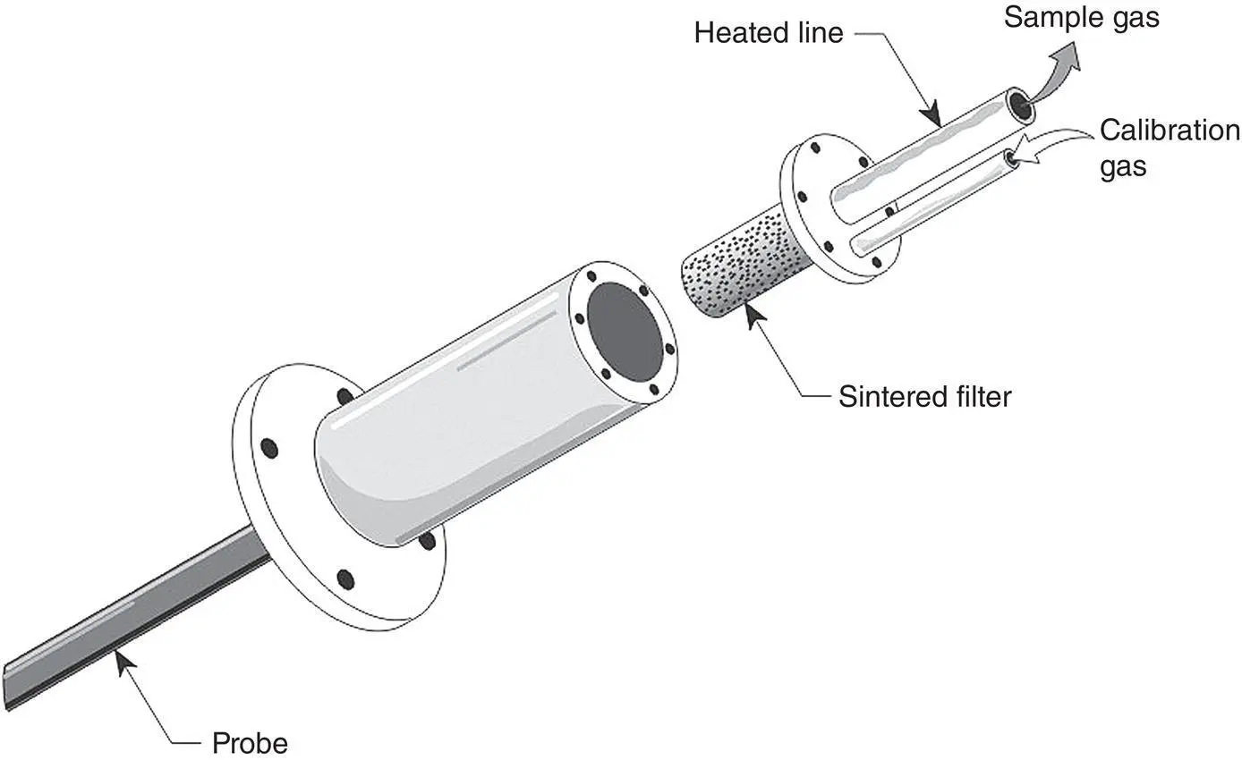
Figure 3‐5 A course filter assembly mounted outside of the stack.
Other variations of the designs as shown in Figure 3‐5are also used. One variation uses a coarse filter of 10–50 μm porosity at the probe tip, but incorporates a 1‐μm‐pore‐size external fine filter at the flange assembly. Another variant uses a bellows valve to close off the external filter from the probe to reduce the amount of gas necessary to perform a probe calibration check.
A major problem associated with the probes illustrated in Figures 3‐4a–c and 3‐5is that the sintered filters still can plug with particulate matter. Another system, designed to minimize this problem, utilizes an inertial filter ( Figure 3‐6).
In the inertial filter system, a pump (usually an eductor pump) pulls the flue gas through an internal cylindrical filter. The internal filter can be made of sintered stainless steel or porous ceramic, usually having a pore size of 2–5 μm. As the flue gas moves down the tube, a sample is pulled off from the filter at a direction perpendicular to the gas flow (radially) using another sampling pump. The gas velocity through the tube can vary from 70 to 100 ft/s, whereas the radial velocity of the gas pulled from the filter may be only 0.005 ft/s. Larger particles in the flue gas are swept through the tube because of their inertia in the gas stream and are exhausted back into the stack. Because of the low radial sample velocity, larger particles are also less likely to break from their streamlines and enter the filter. The 70–100 ft/s flow also aids in sweeping the particles off of the filter surface and back into the gas stream. An inertial filter can be incorporated as part of the probe inside the stack or in a system external to the probe, such as the one shown in Figure 3‐7.
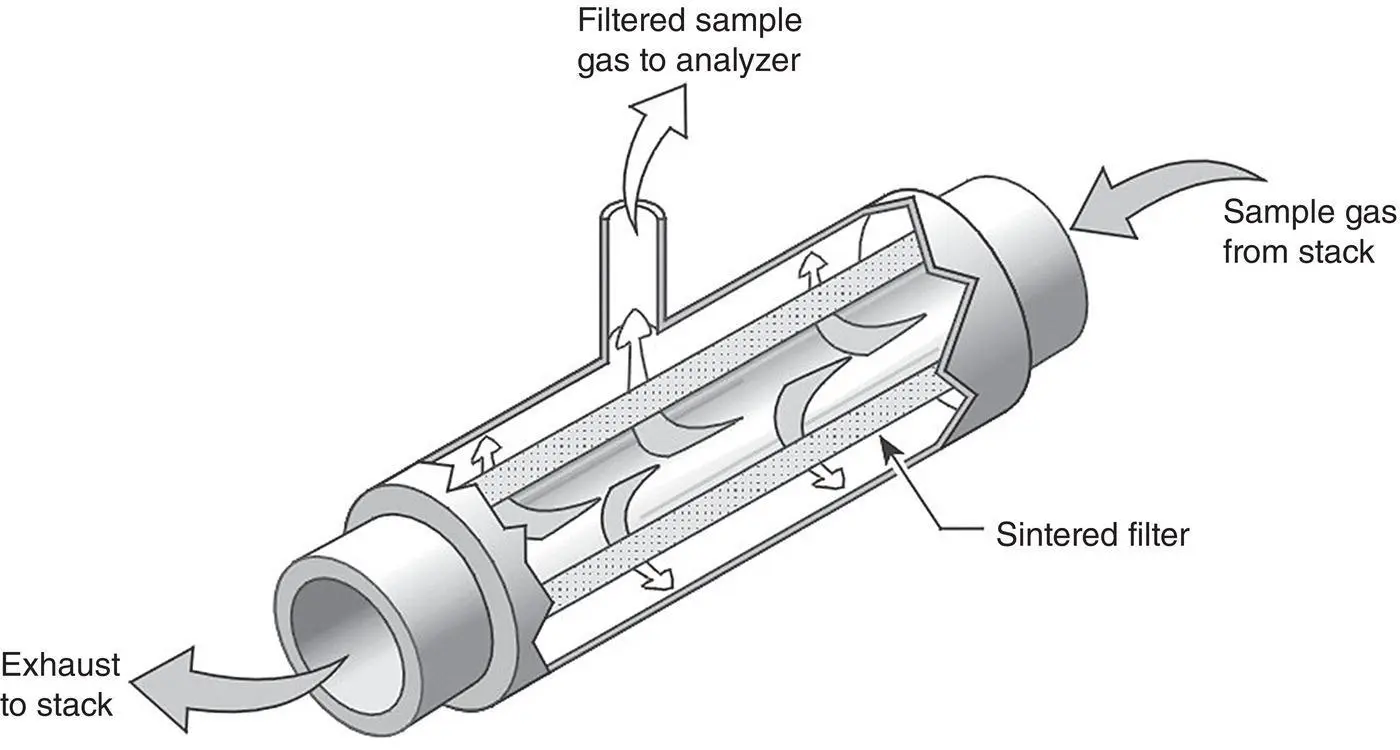
Figure 3‐6 The inertial filter.
Conceptually, this system may appear ideal, but actually, submicron sized particles (<1 μm diameter) can follow the radial sample flow and enter the tubular filter. These embedded particles can further assist in the filtering action to reduce the filter pore size and remove particles down to 0.5 μm diameter from the sample stream. However, this also means that the filter can eventually become plugged.
Filter plugging can be a problem with any fully extractive system. Plugging can be minimized by “blowing back” on the filter using high‐pressure gas, plant air, or steam – air at pressures from 60 to 100 pounds per square inch (psi) is blown back through the filter, opposite to the normal direction of gas flow. The blowback can be pulsed by first pressurizing a surge tank and suddenly releasing the pressure to shock the particulate matter out of the pores of the filter. Depending upon particle characteristics and concentration, filters are blown back at periods of 15 minutes to 8 hours for durations of 5–10 s; 15‐minute blowback cycles are common. Care must be taken in the blowback system so that the blowback gas does not cool the probe to the extent that acids or other gases condense.
Umbilical Line
In a cool/dry system, a heated sample line is used to transport the sample from the probe to other elements in the conditioning system, or in the case of hot/wet systems, directly to the analyzer after particulate removal. The heated sample line (heat‐traced line) is generally incorporated into a tube bundle, or umbilical, which may contain electrical cables and additional tubing to transport zero air, blowback air, and calibration gases. Temperature sensors can also be placed at intervals along the line to monitor the temperature and warn of any reduction in temperature. A typical umbilical tube assembly with a heated wire coiled around the tube bundle is shown in Figure 3‐8.
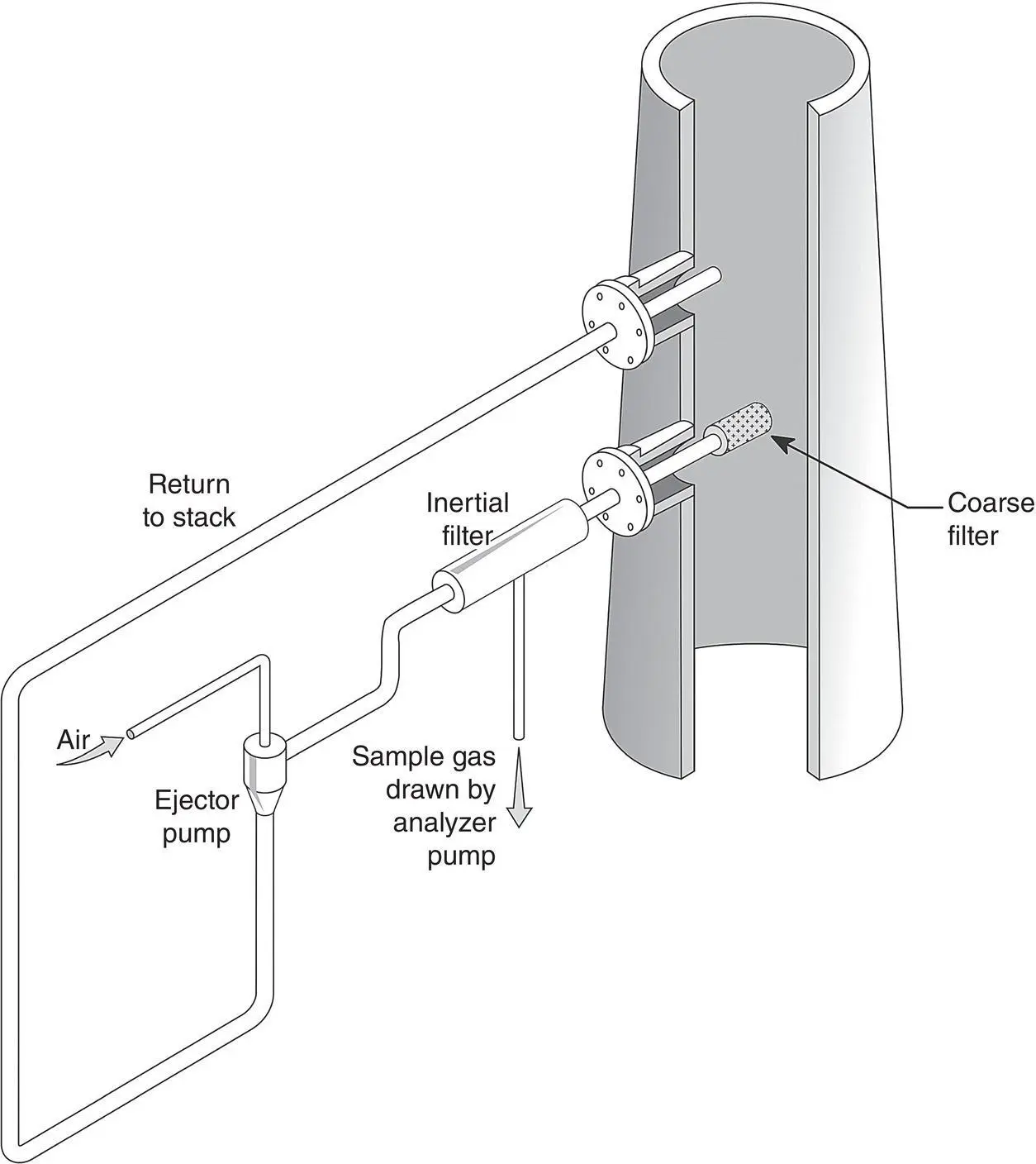
Figure 3‐7 An externally mounted inertial filter.
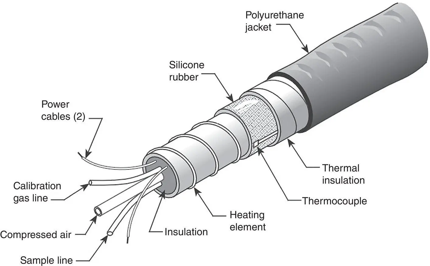
Figure 3‐8 An umbilical assembly external to the stack.
In cool/dry extractive systems, heat‐traced line is used all the way from the probe to the moisture removal system. This distance can be as short as 2–3 ft for stack located systems, but is more commonly 100–250 ft. It is important to insulate and/or heat the junctions between the heat‐traced sample line and the probe and between the line and the moisture removal system; otherwise cold spots can develop that may eventually cause plugging and corrosion. If the moisture removal system is installed at the probe location, or if a dilution extractive system is applied, unheated sample line (or sample line with a lower temperature rating – freeze‐protection line) can be used to transport the sample to the analyzer.
Typical temperatures for extractive‐system heated sample lines are higher than 180 °C. Typical sample line materials are high‐density polyethylene (HDPE – maximum temperature 110 °C), polytetrafluoroethylene (PTFE – maximum temperature 260 °C), perfluoroalkoxy Teflon (PFA – maximum temperature 260 °C), and stainless steel (ss – either uncoated or treated coated with glass (SilcoNert ®)). Heated umbilicals can be operated either at a constant power density or can be self‐limiting (self‐regulating). In self‐limiting lines, a specified minimum operating temperature will be maintained if the ambient temperature falls (e.g. sub‐zero conditions in winter) and will not exceed a specified maximum temperature if the ambient temperature rises. A cross section of a self‐regulated line for a dilution extractive system, with the heating element in the center of the bundle for freeze‐protection, is shown in Figure 3‐9.
This umbilical consists of the following components:
One 3/8″ O.D. PFA Teflon tube heated sample line
One 3/8″ O.D. PFA Teflon tube heated dilution air line
Two 1/4″ O.D. PFA Teflon tube (unheated calibration gas and purge air and spare)
Two 1/4″ O.D. PFA Teflon tube (unheated spares)
Two 3/8″ O.D. PFA Teflon tube (unheated spares)
Electrical lines in the umbilical include the following:
Sample line heater (120 self‐regulating heating cable)
Sample line Type K thermocouple
The low‐temperature self‐regulating heater in the line operates to maintain a temperature of approximately 50 °F, to guard against water condensation in the flue gas sample if the ambient temperature decreases below the dew point of the diluted sample gas (<���−40 °C). The internal heated portion of the bundle is enclosed by a thermal barrier of an aluminum heat transfer tape. The outside of the bundle is enclosed by a flexible, black polyvinyl chloride insulation jacket. In this case, the calibration gas lines are located in the outer, unheated jacket of the bundle. Another option is to provide a separate, unheated umbilical to house the zero air and calibration gas lines.
Although much information has been cataloged on the relative chemical resistance of sample line materials to corrosive gases (McNulty et al. 1974; Podlenski 1984), 316 stainless steel or PFA Teflon are commonly used. Problems can occur with Teflon if the line temperature is too high since its softening temperature is near 250 °C. Efforts to increase sample line temperature to avoid condensation or adsorption sometimes melt the line and the umbilical cable. Furthermore, some gases (such as CO) can permeate through polymeric sample lines (Dunder and Stone 1995), especially at higher temperatures.
Читать дальшеИнтервал:
Закладка:
Похожие книги на «Continuous Emission Monitoring»
Представляем Вашему вниманию похожие книги на «Continuous Emission Monitoring» списком для выбора. Мы отобрали схожую по названию и смыслу литературу в надежде предоставить читателям больше вариантов отыскать новые, интересные, ещё непрочитанные произведения.


Обсуждение, отзывы о книге «Continuous Emission Monitoring» и просто собственные мнения читателей. Оставьте ваши комментарии, напишите, что Вы думаете о произведении, его смысле или главных героях. Укажите что конкретно понравилось, а что нет, и почему Вы так считаете.