Maintenance, Reliability and Troubleshooting in Rotating Machinery
Здесь есть возможность читать онлайн «Maintenance, Reliability and Troubleshooting in Rotating Machinery» — ознакомительный отрывок электронной книги совершенно бесплатно, а после прочтения отрывка купить полную версию. В некоторых случаях можно слушать аудио, скачать через торрент в формате fb2 и присутствует краткое содержание. Жанр: unrecognised, на английском языке. Описание произведения, (предисловие) а так же отзывы посетителей доступны на портале библиотеки ЛибКат.
- Название:Maintenance, Reliability and Troubleshooting in Rotating Machinery
- Автор:
- Жанр:
- Год:неизвестен
- ISBN:нет данных
- Рейтинг книги:4 / 5. Голосов: 1
-
Избранное:Добавить в избранное
- Отзывы:
-
Ваша оценка:
Maintenance, Reliability and Troubleshooting in Rotating Machinery: краткое содержание, описание и аннотация
Предлагаем к чтению аннотацию, описание, краткое содержание или предисловие (зависит от того, что написал сам автор книги «Maintenance, Reliability and Troubleshooting in Rotating Machinery»). Если вы не нашли необходимую информацию о книге — напишите в комментариях, мы постараемся отыскать её.
This broad collection of current rotating machinery topics, written by industry experts, is a must-have for rotating equipment engineers, maintenance personnel, students, and anyone else wanting to stay abreast with current rotating machinery concepts and technology.
Maintenance, Reliability and Troubleshooting in Rotating Machinery
Maintenance, Reliability and Troubleshooting in Rotating Machinery — читать онлайн ознакомительный отрывок
Ниже представлен текст книги, разбитый по страницам. Система сохранения места последней прочитанной страницы, позволяет с удобством читать онлайн бесплатно книгу «Maintenance, Reliability and Troubleshooting in Rotating Machinery», без необходимости каждый раз заново искать на чём Вы остановились. Поставьте закладку, и сможете в любой момент перейти на страницу, на которой закончили чтение.
Интервал:
Закладка:
Temperatures
As most process gases get compressed, they heat up in a predictable way. For a given suction temperature, we should expect a predictable temperature rise due to compression at the discharge nozzle. However, deviations in predicted temperature values can occur, which is why operators need to keep an eye on compressor gas operating temperatures. Temperature levels provide vital clues to the condition of a compressor. High compressor discharge temperature or interstage temperatures can be a sign of compressor degradation or a higher than normal compression ratio, due to system fouling or a restriction.
Takeaway: Gas temperature trending is a simple way of assessing the overall aerodynamic health of a centrifugal compressor.
Bearing temperatures can also provide vital clues to the condition of a centrifugal compressor. An upward trending bearing temperature is a sign that something is changing, such as the bearing’s condition or the oil supply temperature. The most critical bearing temperatures are the thrust bearing pad temperatures. A failure of the thrust bearing pad will result in a catastrophic rotor failure as excessive axial movement occurs, which is why the axial position of the rotor should always be closely monitored and trended.
For an extra level of thrust bearing failure detection, a dual voting (2 out of 2, i.e., 2oo2) arrangement composed or two proximity probes are normally installed on critical compressors. (Note: The proximity probes must be installed axially so that they observe the thrust collar or other integral portion of the shaft surface. Probe targets, such as shaft sleeves, that are not integral to the shaft are not recommended.) Each machine train thrust monitor should be configured in a dual voting configuration, 2 out of 2 (2oo2), which is considered best practice by API 670 to ensure a high level of in machinery protection. In some highly critical applications, an OEM or end user may even request a triple modular redundant (TMR) configuration, 2 out of 3 voting (2oo3), to achieve the required reliability level.
A typical set of safeguards for a centrifugal compressor might include:
A well-written set of operation and start-up procedures to prevent the compressor from operating at any unsafe flow or speeds
Reliable flow and speed control
A reliable surge control system
A reliable vibration and thrust monitoring system
Periodic lubrication monitoring
Periodic field inspections of the compressor and driver
Compressor performance monitoring
The purpose of safeguards is to prevent bad things from occurring. In cases where the consequences of an initial failure can escalate and grow in severity due to a progression of secondary damage, multiple safeguards can be used to mitigate the consequences of a failure by breaking the sequence of unwanted events. Figure 1.7shows a hypothetical installation with a group of safeguards in place to prevent a failure or mitigate the effects of a failure. Without safeguards in place, a failure could progress from internal machinery damage to, in extreme cases, a catastrophic release with the potential to impact the plant or the surrounding community. In general, the greater the consequences of a failure, the more safeguards are required. We must always strive to achieve a balance between cost of safeguards and the risks involved.
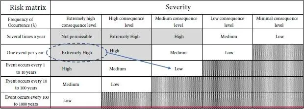
Now let’s use what we’ve learned and consider the risk matrix shown in Table 1.3. The far-left column shows event probability levels and across the top are event consequence levels. For example, the intersection of an “extremely high consequence event” and an event probability of “one event per year” represents an extremely high risk, as highlighted by the dashed oval. The idea of risk control is to design machinery systems so that all risks levels are at acceptable, low levels. If you find a particular risk level to be high during the course of your analysis, you can either reduce its probability of occurrence through machine redesign or by incorporating operating procedures or reduce the consequence level by adding additional protection, such as automatic shutoff valves, barriers, fire protection, etc. Moving the risk level to a cell that is either to the right or down from your starting point is desirable. An optimum outcome is moving your machine’s risk in the general direction of the arrow in Table 1.3, which points down and to the right.
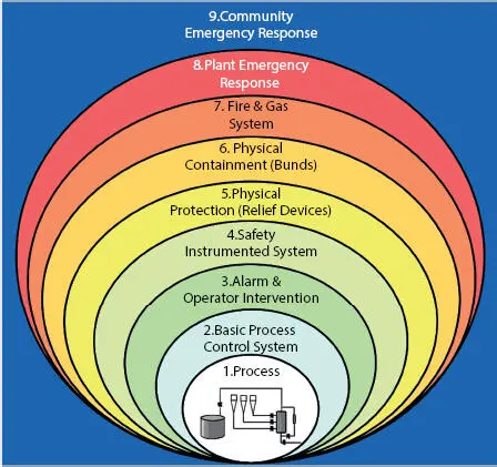
Figure 1.7 A set of safeguards are designed to prevent major events from occurring or to mitigate their effects.
Table 1.3 Here is a risk matrix for a hypothetical process machine. In this table, risk is defined as the frequency of an event occurring times the consequence level of the event (Risk = λ x C). Therefore, the cells in the upper-left corner of the matrix represent the highest levels of risk, and the cells in the lower-right corner represent the lowest levels of risk. Reliability professionals should strive to lower risk levels to acceptable levels using procedures, machine improvements or other safeguards.
It is helpful to drill down to the failure mode level to understand the true nature of your risk. For example, if you have a mechanical seal that is failing more than one a year, causing a costly unit outage (high risk level), then you quickly realize you must improve the reliability of the seal. Other design efforts to reduce risk will likely be ineffective in significantly reducing the failure rate.
Layers of Machinery Protection
A set of safeguards should work together to provide multiple layers of protection ( Figure 1.7) designed to eliminate failures and mitigate the effect of machinery failures. Here is a list of generic safeguards that can be used as a starting point for a review. As you go down the list, the consequences increase in severity. For example, items 1 through 4 represent normal operation, items 5 and 6 go into action if an upset has occurred and some type of automatic action is required for correction, and finally, items 7 through 9 are required when a product release has occurred.
You must decide if this list makes sense in your situation.
1 Detailed operating procedures are recommended in all cases. There should be specific operating procedure for start-ups, shutdowns, and normal operations.
2 A set of operating targets for flow, pressure, and temperature limits help keep your equipment away from unsafe operating conditions
3 Reliable process control systemsFlow, pressure, and speed control
4 An alarm and operator Intervention planPeriodic walk-through inspectionsMachine alarms (temp, vibration, speed, etc.) to alert the operating of an unsafe condition
5 Safety Instrumented systems (SIS) for high consequence events, such as:Overspeed trip systemsTemp and vibration monitoring system set to tripAutomatic surge control
6 Physical ProtectionRelief valves for overpressure eventsElectrical breakersMechanical overspeed trips
7 At this point of our hypothetical scenario, there has been a full loss of containment. The potential released volume and flammability of the liquid or gas released will dictate the severity of the event. Physical containments can be used for mitigation, such as:Isolation valves (with fusible links) & battery limit valvesDikesDitchesBarriers and walls
8 If the severity of a release is deemed great enough then a plant emergency response plan may be required.
Читать дальшеИнтервал:
Закладка:
Похожие книги на «Maintenance, Reliability and Troubleshooting in Rotating Machinery»
Представляем Вашему вниманию похожие книги на «Maintenance, Reliability and Troubleshooting in Rotating Machinery» списком для выбора. Мы отобрали схожую по названию и смыслу литературу в надежде предоставить читателям больше вариантов отыскать новые, интересные, ещё непрочитанные произведения.


Обсуждение, отзывы о книге «Maintenance, Reliability and Troubleshooting in Rotating Machinery» и просто собственные мнения читателей. Оставьте ваши комментарии, напишите, что Вы думаете о произведении, его смысле или главных героях. Укажите что конкретно понравилось, а что нет, и почему Вы так считаете.