Ibrahim Dogan - Advanced PIC Microcontroller Projects in C
Здесь есть возможность читать онлайн «Ibrahim Dogan - Advanced PIC Microcontroller Projects in C» весь текст электронной книги совершенно бесплатно (целиком полную версию без сокращений). В некоторых случаях можно слушать аудио, скачать через торрент в формате fb2 и присутствует краткое содержание. Город: Burlington, Год выпуска: 2008, ISBN: 2008, Издательство: Elsevier Ltd, Жанр: Программирование, Компьютерное железо, на английском языке. Описание произведения, (предисловие) а так же отзывы посетителей доступны на портале библиотеки ЛибКат.

- Название:Advanced PIC Microcontroller Projects in C
- Автор:
- Издательство:Elsevier Ltd
- Жанр:
- Год:2008
- Город:Burlington
- ISBN:978-0-7506-8611-2
- Рейтинг книги:5 / 5. Голосов: 1
-
Избранное:Добавить в избранное
- Отзывы:
-
Ваша оценка:
Advanced PIC Microcontroller Projects in C: краткое содержание, описание и аннотация
Предлагаем к чтению аннотацию, описание, краткое содержание или предисловие (зависит от того, что написал сам автор книги «Advanced PIC Microcontroller Projects in C»). Если вы не нашли необходимую информацию о книге — напишите в комментариях, мы постараемся отыскать её.
• Features 20 complete, tried and test projects
• Includes a CD-ROM of all the programs, hex listings, diagrams, and data sheets
Advanced PIC Microcontroller Projects in C — читать онлайн бесплатно полную книгу (весь текст) целиком
Ниже представлен текст книги, разбитый по страницам. Система сохранения места последней прочитанной страницы, позволяет с удобством читать онлайн бесплатно книгу «Advanced PIC Microcontroller Projects in C», без необходимости каждый раз заново искать на чём Вы остановились. Поставьте закладку, и сможете в любой момент перейти на страницу, на которой закончили чтение.
Интервал:
Закладка:
Table 8.12: Example HID descriptor
| Offset | Field | Value | Description |
|---|---|---|---|
| 0 | bLength | 9 | Descriptor size is 9 bytes |
| 1 | bDescriptorType | 0x21 | HID (0x21) |
| 2 | bcdHID | 0x0110 | Class version 1.1 |
| 4 | bCountryCode | 0 | No special country dependent code |
| 5 | bNumDescriptors | 1 | Number of additional descriptors |
| 6 | bDescriptorType | REPORT | Type of additional descriptor |
| 7 | wDescriptorLength | 5 | Length of additional descriptor |
8.4.5 Endpoint Descriptors
Table 8.13 shows the format of the endpoint descriptor.
bLength is the length of the device descriptor.
bDescriptorType is the descriptor type.
bEndpointAddress is the address of the endpoint.
bmAttributes specifies what type of endpoint it is.
wMaxPacketSize is the maximum packet size.
bInterval specifies how often the endpoint should be polled (in ms).
Table 8.13: Endpoint descriptor
| Offset | Field | Size | Description |
|---|---|---|---|
| 0 | bLength | 1 | Descriptor size in bytes |
| 1 | bDescriptorType | 1 | Endpoint (0x05) |
| 2 | bcdEndpointAddress | 1 | Endpoint address |
| 4 | bmAttributes | 1 | Type of endpoint |
| 5 | wMaxPacketSize | 2 | Max packet size |
| 6 | bInterval | 1 | Polling interval |
Table 8.14 shows an example endpoint descriptor for a mouse device. The length of the descriptor is 7 bytes ( bLength =7), and the descriptor type is 0x05 ( bDescriptorType =0x05). The endpoint address is 0x50 ( bEndpointAddress =0x50). The endpoint is to be used as an interrupt endpoint ( bmAttributes =0x03). The maximum packet size is set to 2 ( wMaxPacketSize =0x02) to indicate that packets longer than 2 bytes will not be sent from the endpoint. The endpoint should be polled at least once every 20ms ( bInterval =0x14).
Table 8.14: Example endpoint descriptor
| Offset | Field | Size | Description |
|---|---|---|---|
| 0 | bLength | 7 | Descriptor size in bytes |
| 1 | bDescriptorType | 0x05 | Endpoint (0x05) |
| 2 | bcdEndpointAddress | 0x50 | Endpoint address |
| 4 | bmAttributes | 0x03 | Interrupt type endpoint |
| 5 | wMaxPacketSize | 0x0002 | Max packet size is 2 |
| 6 | bInterval | 0x14 | Polling interval is 20ms |
8.5 PIC18 Microcontroller USB Bus Interface
Some of the PIC18 microcontrollers support USB interface directly. For example, the PIC18F4550 microcontroller contains a full-speed and low-speed compatible USB interface that allows communication between a host PC and the microcontroller. In the USB projects in this chapter we will use the PIC18F4550 microcontroller.
Figure 8.8 is an overview of the USB section of the PIC18F4550 microcontroller. PORTC pins RC4 (pin 23) and RC5 (pin 24) are used for USB interface. RC4 is the USB data D– pin, and RC5 is the USB data D+ pin. Internal pull-up resistors are provided which can be disabled (setting UPUEN =0) if desired and external pull-up resistors can be used instead. For full-speed operation an internal or external resistor should be connected to data pin D+, and for low-speed operation an internal or external resistor should be connected to data pin D–.
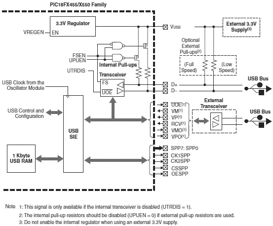
Figure 8.8: PIC18F4550 microcontroller USB overview
Operation of the USB module is configured using three control registers, and a total of twenty-two registers are used to manage the actual USB transactions. Configuration of these registers is a highly complex task and is not covered in this book. Interested readers should refer to the PIC18F4550 data sheet and to books on USB internals. In this chapter we are using the mikroC language USB library functions to implement USB transactions. The details of these functions are given in the next section.
8.6 mikroC Language USB Bus Library Functions
The mikroC language supports a number of functions for USB HID-type communications. Each project based on the USB library should include a descriptor source file which contains vendor ID and name, product ID and name, report length, and other relevant information. To create a descriptor source file we can use mikroC’s integrated USB HID terminal tool (see Tools→HID Terminal ). The default name for descriptor file is USBdsc.c , but it can be renamed if required. The USBdsc.c file must be included in USB-based projects either via the mikroC IDE tool, or as an #include option in the program source file.
The mikroC language supports the following USB bus library functions when a PIC microcontroller with built-in USB is used (e.g., PIC18F4550), and port pins RC4 and RC5 are connected to the D+ and D– pins of the USB connector respectively:
Hid_Enable: This function enables USB communication and requires two arguments: the read-buffer address and the write-buffer address. It must be called before any other functions of the USB library, and it returns no data.
Hid_Read: This function receives data from the USB bus and stores it in the receive-buffer. It has no arguments but returns the number of characters received.
Hid_Write: This function sends data from the write-buffer to the USB bus. The name of the buffer (the same buffer used in the initialization) and the length of the data to be sent must be specified as arguments to the function. The function does not return any data.
Hid_Disable: This function disables the USB data transfer. It has no arguments and returns no data.
The USB interface of a PIC18F4550 microcontroller is shown in Figure 8.9. As the figure shows, the interface is very simple. In addition to the power supply and ground pins, it requires just two pins to be connected to the USB connector. The microcontroller receives power from the USB port.
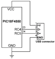
Figure 8.9: PIC18F4550 USB interface
PROJECT 8.1 — USB-Based Microcontroller Output Port
This project describes the design of a USB-based microcontroller output port. A PIC18F4550 microcontroller is interfaced to a PC through a USB cable. A Visual Basic program runs on the PC and sends commands to the microcontroller through the USB bus, asking the microcontroller to set/reset the I/O bits of its PORTB.
The block diagram of the project is shown in Figure 8.10. The circuit diagram is given in Figure 8.11. The USB lines of the PIC18F4550 microcontroller are connected to a USB connector. The microcontroller is powered from the USB line (i.e., no external power supply is required). This makes the design of USB-based products relatively cheap and very attractive in applications where the total power consumption is below 100mA. The microcontroller is operated from an 8MHz crystal.
Читать дальшеИнтервал:
Закладка:
Похожие книги на «Advanced PIC Microcontroller Projects in C»
Представляем Вашему вниманию похожие книги на «Advanced PIC Microcontroller Projects in C» списком для выбора. Мы отобрали схожую по названию и смыслу литературу в надежде предоставить читателям больше вариантов отыскать новые, интересные, ещё непрочитанные произведения.


Обсуждение, отзывы о книге «Advanced PIC Microcontroller Projects in C» и просто собственные мнения читателей. Оставьте ваши комментарии, напишите, что Вы думаете о произведении, его смысле или главных героях. Укажите что конкретно понравилось, а что нет, и почему Вы так считаете.