Ibrahim Dogan - Advanced PIC Microcontroller Projects in C
Здесь есть возможность читать онлайн «Ibrahim Dogan - Advanced PIC Microcontroller Projects in C» весь текст электронной книги совершенно бесплатно (целиком полную версию без сокращений). В некоторых случаях можно слушать аудио, скачать через торрент в формате fb2 и присутствует краткое содержание. Город: Burlington, Год выпуска: 2008, ISBN: 2008, Издательство: Elsevier Ltd, Жанр: Программирование, Компьютерное железо, на английском языке. Описание произведения, (предисловие) а так же отзывы посетителей доступны на портале библиотеки ЛибКат.

- Название:Advanced PIC Microcontroller Projects in C
- Автор:
- Издательство:Elsevier Ltd
- Жанр:
- Год:2008
- Город:Burlington
- ISBN:978-0-7506-8611-2
- Рейтинг книги:5 / 5. Голосов: 1
-
Избранное:Добавить в избранное
- Отзывы:
-
Ваша оценка:
Advanced PIC Microcontroller Projects in C: краткое содержание, описание и аннотация
Предлагаем к чтению аннотацию, описание, краткое содержание или предисловие (зависит от того, что написал сам автор книги «Advanced PIC Microcontroller Projects in C»). Если вы не нашли необходимую информацию о книге — напишите в комментариях, мы постараемся отыскать её.
• Features 20 complete, tried and test projects
• Includes a CD-ROM of all the programs, hex listings, diagrams, and data sheets
Advanced PIC Microcontroller Projects in C — читать онлайн бесплатно полную книгу (весь текст) целиком
Ниже представлен текст книги, разбитый по страницам. Система сохранения места последней прочитанной страницы, позволяет с удобством читать онлайн бесплатно книгу «Advanced PIC Microcontroller Projects in C», без необходимости каждый раз заново искать на чём Вы остановились. Поставьте закладку, и сможете в любой момент перейти на страницу, на которой закончили чтение.
Интервал:
Закладка:
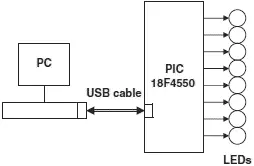
Figure 8.10: Block diagram of the project
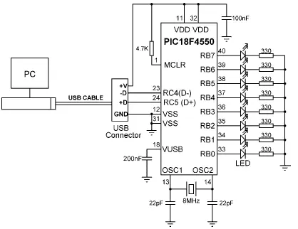
Figure 8.11: Circuit diagram of the project
The PORTB pins of the microcontroller are connected to LEDs so we can see the state changes as commands are sent from the PC. This makes testing the project very easy. Note that a capacitor (about 200nF) should be connected between the VUSB pin (pin 18) of the microcontroller and the ground for stability.
The project software consists of two parts: the PC software, and the microcontroller software. Both are described in this section.
The PC Software
The PC software is based on Visual Basic. It is assumed that the user has elementary knowledge of Visual Basic programming language. Instruction in programming using the Visual Basic language is beyond the scope of this book, and interested readers should refer to various books available on this topic.
The source program listing and the executables of the programs are given on the CDROM distributed with this book. Readers who do not want to do any programming can use or modify the given programs.
The Visual Basic program in this example consists of a single form as shown in Figure 8.12. The required PORTB data should be entered in decimal in the text box, and then the command button CLICK TO SEND should be clicked with the mouse. For example, entering decimal number 15 will turn on the LEDs connected to port pins RB0,RB1,RB2, and RB3 of PORTB.
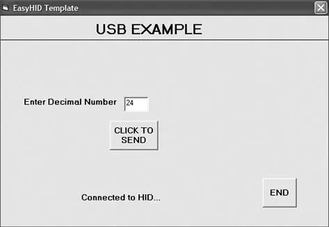
Figure 8.12: The PC Visual Basic form
The program sends the entered number to the microcontroller as a packet consisting of four characters in the following format:
P = nT
where character P indicates the start of data, n is the byte to be sent to PORTB, and T is the terminator character.
For example, if bits 3 and 4 of PORTB are to be set, i.e., PORTB = “00011000,” then the Visual Basic program sends packet P = 24T (number 24 is sent as a single binary byte and not as two ASCII bytes) to the microcontroller over the USB link. The bottom part of the form displays the connection status.
The Visual Basic program used in this section is based on the USB utility known as EasyHID USB Wizard, developed by Mecanique, and can be downloaded free of charge from their web site (www.mecanique.co.uk). EasyHID is designed to work with USB 2.0, and there is no need to develop a driver, as the XP operating system is shipped with a HID-based USB driver. This utility generates Visual Basic, Visual C++, or Borland Delphi template codes for the PC end of a USB application using an HID-type device interface. In addition, the utility can generate USB template code for the PIC18F4550 and similar microcontrollers, based on the Proton Development Suite (www.crownhill.co.uk), Swordish PIC Basic, or PicBasic Pro (www.melabs.com) programming languages. The generated codes can be expanded with the user code to implement the required application.
The steps in generating a Visual Basic code template follow:
• Load the EasyHID zip file from the Mecanique web site by clicking on “Download EasyHID as a Standalone Application”
• Extract the files and install the application by double-clicking on SETUP.
• When the program has started, you should see a form as shown in Figure 8.13. Enter your data in the fields Company Name, Product Name, and the optional Serial Number.
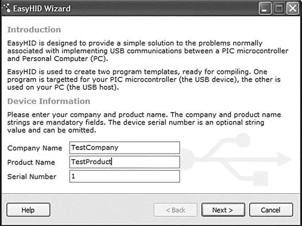
Figure 8.13: EasyHID first form
• Enter your Vendor ID (VID) and Product ID (PID) as shown in the form in Figure 8.14. Vendor IDs are unique throughout the world and are issued by the USB implementers (www.usb.org) at a cost. Mecanique owns a Vendor ID and can issue you a set of Product IDs at low cost so your products can be shipped all over the world with unique VID and PID combinations. In this example, VID=4660 and PID=1 are selected for test purposes.
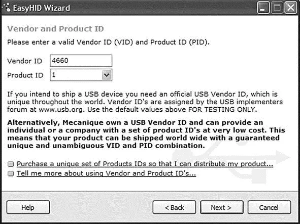
Figure 8.14: EasyHID VID and PID entry form
• Clicking Next displays the form shown in Figure 8.15. The important parameters here are the output and input buffer sizes, which specify the number of bytes to be sent and received respectively between the PC and the microcontroller during USB data transactions. In this example, 4 bytes are chosen for both fields (our output is in the format P=nT, which is 4 bytes).
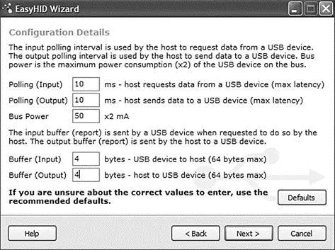
Figure 8.15: EasyHID input-output buffer selection
• In the next form (see Figure 8.16), select a location for the generated files, choose the microcontroller compiler to be used (this field is not important, as we are only generating code for Visual Basic (i.e., the PC end), choose the microcontroller type, and finally select Visual Basic as the language to be used.
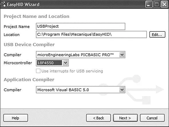
Figure 8.16: EasyHID output folder, microcontroller type, and host compiler selection
• Clicking Next generates Visual Basic and microcontroller code templates in the selected directories (see the final form in Figure 8.17).
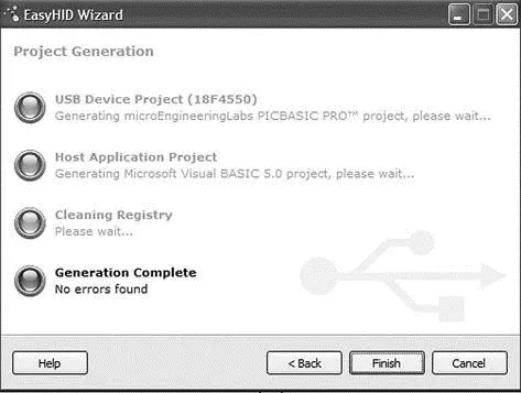
Figure 8.17: EasyHID last form
Figure 8.18 shows the Visual Basic files generated by the EasyHID wizard. The files basically consist of a blank form (FormMain.frm), a module file (mcHIDInterface. BAS), and a project file (USBProject.vbp).
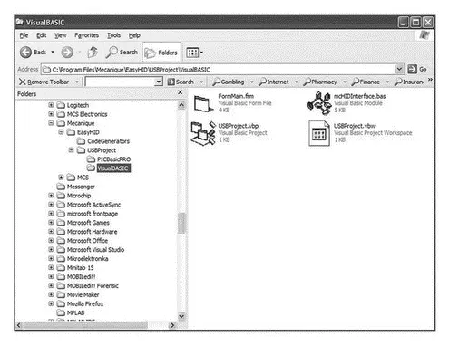
Figure 8.18: Files generated by the EasyHID wizard
The files generated by the EasyHID wizard have been modified for our project as follows:
• The blank form has been modified to display the various controls shown in Figure 8.12.
• Messages are added to the program to display when a USB device is plugged into or unplugged from the PC.
• A subroutine has been added to read the data entered by the user and then send this data to the microcontroller over the USB bus when the button CLICK TO SEND is clicked. This code is as follows:
Private Sub Command2_Click()
BufferOut(0) = 0 ' first by is always the report ID
BufferOut(1) = Asc("P") ' first data item (“P”)
BufferOut(2) = Asc("=") ' second data item (“=”)
BufferOut(3) = Val(txtno) ' third data item (number to send)
BufferOut(4) = Asc("T") ' fourth data item (“T”)
' write the data (don't forget, pass the whole array)...
hidWriteEx VendorID, ProductID, BufferOut(0)
lblstatus = "Data sent..."
End Sub
BufferOut stores the data to be sent to the microcontroller over the USB bus. Notice that the first byte of this buffer is the report ID and must be set to 0. The actual data starts from address BufferOut(1) of the array and the data sent is in the format P=nT as described before. After the data is sent, the message “Data sent…” appears at the bottom part of the display.
Читать дальшеИнтервал:
Закладка:
Похожие книги на «Advanced PIC Microcontroller Projects in C»
Представляем Вашему вниманию похожие книги на «Advanced PIC Microcontroller Projects in C» списком для выбора. Мы отобрали схожую по названию и смыслу литературу в надежде предоставить читателям больше вариантов отыскать новые, интересные, ещё непрочитанные произведения.


Обсуждение, отзывы о книге «Advanced PIC Microcontroller Projects in C» и просто собственные мнения читателей. Оставьте ваши комментарии, напишите, что Вы думаете о произведении, его смысле или главных героях. Укажите что конкретно понравилось, а что нет, и почему Вы так считаете.