Ibrahim Dogan - Advanced PIC Microcontroller Projects in C
Здесь есть возможность читать онлайн «Ibrahim Dogan - Advanced PIC Microcontroller Projects in C» весь текст электронной книги совершенно бесплатно (целиком полную версию без сокращений). В некоторых случаях можно слушать аудио, скачать через торрент в формате fb2 и присутствует краткое содержание. Город: Burlington, Год выпуска: 2008, ISBN: 2008, Издательство: Elsevier Ltd, Жанр: Программирование, Компьютерное железо, на английском языке. Описание произведения, (предисловие) а так же отзывы посетителей доступны на портале библиотеки ЛибКат.

- Название:Advanced PIC Microcontroller Projects in C
- Автор:
- Издательство:Elsevier Ltd
- Жанр:
- Год:2008
- Город:Burlington
- ISBN:978-0-7506-8611-2
- Рейтинг книги:5 / 5. Голосов: 1
-
Избранное:Добавить в избранное
- Отзывы:
-
Ваша оценка:
Advanced PIC Microcontroller Projects in C: краткое содержание, описание и аннотация
Предлагаем к чтению аннотацию, описание, краткое содержание или предисловие (зависит от того, что написал сам автор книги «Advanced PIC Microcontroller Projects in C»). Если вы не нашли необходимую информацию о книге — напишите в комментариях, мы постараемся отыскать её.
• Features 20 complete, tried and test projects
• Includes a CD-ROM of all the programs, hex listings, diagrams, and data sheets
Advanced PIC Microcontroller Projects in C — читать онлайн бесплатно полную книгу (весь текст) целиком
Ниже представлен текст книги, разбитый по страницам. Система сохранения места последней прочитанной страницы, позволяет с удобством читать онлайн бесплатно книгу «Advanced PIC Microcontroller Projects in C», без необходимости каждый раз заново искать на чём Вы остановились. Поставьте закладку, и сможете в любой момент перейти на страницу, на которой закончили чтение.
Интервал:
Закладка:
Resume: A suspended device is woken up by reversing the polarity of the signal on the data lines for at least 20ms, followed by a low-speed EOP signal.
8.3 USB Bus Communication
USB is a host-centric connectivity system where the host dictates the use of the USB bus. Each device on the bus is assigned a unique USB address, and no slave device can assert a signal on the bus until the host asks for it. When a new USB device is plugged into a bus, the USB host uses address 0 to ask basic information from the device. Then the host assigns it a unique USB address. After the host asks for and receives further information about the device, such as the name of the manufacturer, device capabilities, and product ID, two-way transactions on the bus can begin.
8.3.1 Packets
Data is transmitted on a USB bus in packets. A packet starts with a sync pattern to allow the receiver clock to synchronize with the data. The data bytes of the packet follow, ending with an end of packet signal.
A packet identifier (PID) byte immediately follows the sync field of every USB packet. A PID itself is 4 bits long, and the 4 bits are repeated in a complemented form. There are seventeen different PID values, as shown in Table 8.4. These include one reserved value and one that is used twice, with two different meanings.
Table 8.4: PID values
| PID type | PID name | Bits | Description |
|---|---|---|---|
| Token | OUT | 1110 0001 | Host to device transaction |
| IN | 0110 1001 | Device to host transaction | |
| SOF | 1010 0101 | Start of frame | |
| SETUP | 0010 1101 | Setup command | |
| Data | DATA0 | 1100 0011 | Data packet PID even |
| DATA1 | 0100 1011 | Data packet PID odd | |
| DATA2 | 1000 0111 | Data packet PID high speed | |
| MDATA | 0000 1111 | Data packet PID high speed | |
| Handshake | ACK | 1101 0010 | Receiver accepts packet |
| NAK | 0101 1010 | Receiver does not accept packet | |
| STALL | 0001 1110 | Stalled | |
| NYET | 1001 0110 | No response from receiver | |
| Special | PRE | 0011 1100 | Host preamble |
| ERR | 0011 1100 | Split transaction error | |
| SPLIT | 0111 1000 | High-speed split transaction | |
| PING | 1011 0100 | High-speed flow control | |
| Reserved | 1111 0000 | Reserved |
There are four packet formats, based on which PID is at the start of the packet: token packets, data packets, handshake packets, and special packets.
Figure 8.4 shows the format of a token packet, which is used for OUT, IN, SOF (start of frame), and SETUP. The packet contains a 7-bit address, a 4-bit ENDP (endpoint number), a 5-bit CRC checksum, and an EOP (end of packet).

Figure 8.4: Token packet
A data packet is used for DATA0, DATA1, DATA2, and MDATA data transactions. The packet format is shown in Figure 8.5 and consists of the PID, 0–1024 bytes of data, a 2-byte CRC checksum, and an EOP.
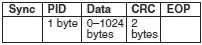
Figure 8.5: Data packet
Figure 8.6 shows the format of a handshake packet, which is used for ACK, NAK, STALL, and NYET. ACK is used when a receiver acknowledges that it has received an error-free data packet. NAK is used when the receiving device cannot accept the packet. STALL indicates when the endpoint is halted, and NYET is used when there is no response from the receiver.

Figure 8.6: Handshake packet
8.3.2 Data Flow Types
Data can be transferred on a USB bus in four ways: bulk transfer, interrupt transfer, isochronous transfer, and control transfer.
Bulk transfers are designed to transfer large amounts of data with error-free delivery and no guarantee of bandwidth. If an OUT endpoint is defined as using bulk transfers, then the host will transfer data to it using OUT transactions. Similarly, if an IN endpoint is defined as using bulk transfers, then the host will transfer data from it using IN transactions. In general, bulk transfers are used where a slow rate of transfer is not a problem. The maximum packet size in a bulk transfer is 8 to 64 packets at full speed, and 512 packets at high speed (bulk transfers are not allowed at low speeds).
Interrupt transfers are used to transfer small amounts of data with a high bandwidth where the data must be transferred as quickly as possible with no delay. Note that interrupt transfers have nothing to do with interrupts in computer systems. Interrupt packets can range in size from 1 to 8 bytes at low speed, from 1 to 64 bytes at full speed, and up to 1024 bytes at high speed.
Isochronous transfers have a guaranteed bandwidth, but error-free delivery is not guaranteed. This type of transfer is generally used in applications, such as audio data transfer, where speed is important but the loss or corruption of some data is not. An isochronous packet may contain 1023 bytes at full speed or up to 1024 bytes at high speed (isochronous transfers are not allowed at low speeds).
A control transfer is a bidirectional data transfer, using both IN and OUT endpoints. Control transfers are generally used for initial configuration of a device by the host. The maximum packet size is 8 bytes at low speed, 8 to 64 bytes at full speed, and 64 bytes at high speed. A control transfer is carried out in three stages: SETUP, DATA, and STATUS.
8.3.3 Enumeration
When a device is plugged into a USB bus, it becomes known to the host through a process called enumeration. The steps of enumeration are:
• When a device is plugged in, the host becomes aware of it because one of the data lines (D+ or D–) becomes logic high.
• The host sends a USB reset signal to the device to place the device in a known state. The reset device responds to address 0.
• The host sends a request on address 0 to the device to find out its maximum packet size using a Get Descriptor command.
• The device responds by sending a small portion of the device descriptor.
• The host sends a USB reset again.
• The host assigns a unique address to the device and sends a Set Address request to the device. After the request is completed, the device assumes the new address. At this point the host is free to reset any other newly plugged-in devices on the bus.
• The host sends a Get Device Descriptor request to retrieve the complete device descriptor, gathering information such as manufacturer, type of device, and maximum control packet size.
• The host sends a Get Configuration Descriptors request to receive the device’s configuration data, such as power requirements and the types and number of interfaces supported.
• The host may request any additional descriptors from the device.
The initial communication between the host and the device is carried out using the control transfer type of data flow.
Initially, the device is addressed, but it is in an unconfigured state. After the host gathers enough information about the device, it loads a suitable device driver which configures the device by sending it a Set Configuration request. At this point the device has been configured, and it is ready to respond to device-specific requests (i.e., it can receive data from and send data to the host).
Читать дальшеИнтервал:
Закладка:
Похожие книги на «Advanced PIC Microcontroller Projects in C»
Представляем Вашему вниманию похожие книги на «Advanced PIC Microcontroller Projects in C» списком для выбора. Мы отобрали схожую по названию и смыслу литературу в надежде предоставить читателям больше вариантов отыскать новые, интересные, ещё непрочитанные произведения.


Обсуждение, отзывы о книге «Advanced PIC Microcontroller Projects in C» и просто собственные мнения читателей. Оставьте ваши комментарии, напишите, что Вы думаете о произведении, его смысле или главных героях. Укажите что конкретно понравилось, а что нет, и почему Вы так считаете.