Ibrahim Dogan - Advanced PIC Microcontroller Projects in C
Здесь есть возможность читать онлайн «Ibrahim Dogan - Advanced PIC Microcontroller Projects in C» весь текст электронной книги совершенно бесплатно (целиком полную версию без сокращений). В некоторых случаях можно слушать аудио, скачать через торрент в формате fb2 и присутствует краткое содержание. Город: Burlington, Год выпуска: 2008, ISBN: 2008, Издательство: Elsevier Ltd, Жанр: Программирование, Компьютерное железо, на английском языке. Описание произведения, (предисловие) а так же отзывы посетителей доступны на портале библиотеки ЛибКат.

- Название:Advanced PIC Microcontroller Projects in C
- Автор:
- Издательство:Elsevier Ltd
- Жанр:
- Год:2008
- Город:Burlington
- ISBN:978-0-7506-8611-2
- Рейтинг книги:5 / 5. Голосов: 1
-
Избранное:Добавить в избранное
- Отзывы:
-
Ваша оценка:
Advanced PIC Microcontroller Projects in C: краткое содержание, описание и аннотация
Предлагаем к чтению аннотацию, описание, краткое содержание или предисловие (зависит от того, что написал сам автор книги «Advanced PIC Microcontroller Projects in C»). Если вы не нашли необходимую информацию о книге — напишите в комментариях, мы постараемся отыскать её.
• Features 20 complete, tried and test projects
• Includes a CD-ROM of all the programs, hex listings, diagrams, and data sheets
Advanced PIC Microcontroller Projects in C — читать онлайн бесплатно полную книгу (весь текст) целиком
Ниже представлен текст книги, разбитый по страницам. Система сохранения места последней прочитанной страницы, позволяет с удобством читать онлайн бесплатно книгу «Advanced PIC Microcontroller Projects in C», без необходимости каждый раз заново искать на чём Вы остановились. Поставьте закладку, и сможете в любой момент перейти на страницу, на которой закончили чтение.
Интервал:
Закладка:
The USB is a high-speed serial interface that can also provide power to devices connected to it. A USB bus supports up to 127 devices (limited by the 7-bit address field — note that address 0 is not used as it has a special purpose) connected through a four-wire serial cable of up to three or even five meters in length. Many USB devices can be connected to the same bus with hubs, which can have 4, 8, or even 16 ports. A device can be plugged into a hub which is plugged into another hub, and so on. The maximum number of tiers permitted is six. According to the specification, the maximum distance of a device from its host is about thirty meters, accomplished by using five hubs. For longer-distance bus communications, other methods such as use of Ethernet are recommended.
The USB bus specification comes in two versions: the earlier version, USB1.1, supports 11Mbps, while the new version, USB 2.0, supports up to 480Mbps. The USB specification defines three data speeds:
• Low speed — 1.5Mb/sec
• Full speed — 12Mb/sec
• High speed — 480Mb/sec
The maximum power available to an external device is limited to about 100mA at 5.0V.
USB is a four-wire interface implemented using a four-core shielded cable. Two types of connectors are specified and used: Type A and Type B. Figure 8.1 shows typical USB connectors. Figure 8.2 shows the pin-out of the USB connectors.
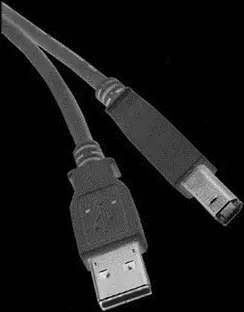
Figure 8.1: USB connectors
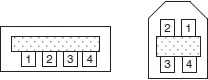
Figure 8.2: Pin-out of USB connectors
The signal wire colors are specified. The pins and wire colors of a Type A or Type B connector are given in Table 8.1.
Table 8.1: USB connector pin assignments
| Pin no. | Name | Color |
|---|---|---|
| 1 | +5.0V | Red |
| 2 | Data– | White |
| 3 | Data+ | Green |
| 4 | Ground | Black |
The specification also defines a mini-B connector, mainly used in smaller portable electronic devices such as cameras and other handheld devices. This connector has a fifth pin called ID, though this pin is not used. The pin assignment and wire colors of a mini-B connector are given in Table 8.2.
Table 8.2: Mini USB pin assignments
| Pin no. | Name | Color |
|---|---|---|
| 1 | +5.0V | Red |
| 2 | –Data | White |
| 3 | +Data | Green |
| 4 | Not used | – |
| 5 | Ground | Black |
Two of the pins, Data+ and Data–, form a twisted pair and carry differential data signals and some single-ended data states.
USB signals are bi-phase, and signals are sent from the host computer using the NRZI (non-return to zero inverted) data encoding technique. In this technique, the signal level is inverted for each change to a logic 0. The signal level for a logic 1 is not changed. A 0 bit is “stuffed” after every six consecutive ones in the data stream to make the data dynamic (this is called bit stuffing because the extra bit lengthens the data stream). Figure 8.3 shows how the NRZI is implemented.
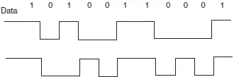
Figure 8.3: NRZI data
A packet of data transmitted by the host is sent to every device connected to the bus, traveling downward through the chain of hubs. All the devices receive the signal, but only one of them, the addressed one, accepts the data. Conversely, only one device at any time can transmit to the host, and the data travels upward through the chain of hubs until it reaches the host.
USB devices attached to the bus may be full-custom devices, requiring a full-custom device driver, or they may belong to a device class. Device classes enable the same device driver to be used for several devices having similar functionalities. For example, a printer device has the device class 0x07, and most printers use drivers of this type.
The most common device classes are given in Table 8.3. The USB human interface device (HID) class is of particular interest, as it is used in the projects in this chapter.
Table 8.3: USB device classes
| Device class | Description | Example device |
|---|---|---|
| 0x00 | Reserved | – |
| 0x01 | USB audio device | Sound card |
| 0x02 | USB communications device | Modem, fax |
| 0x03 | USB human interface device | Keyboard, mouse |
| 0x07 | USB printer device | Printer |
| 0x08 | USB mass storage device | Memory card, flash drive |
| 0x09 | USB hub device | Hubs |
| 0x0B | USB smart card reader device | Card reader |
| 0x0E | USB video device | Webcam, scanner |
| 0xE0 | USB wireless device | Bluetooth |
Some common USB terms are:
Endpoint: An endpoint is either a source or a sink of data. A single USB device can have a number of endpoints, the limit being sixteen IN and sixteen OUT endpoints.
Transaction: A transaction is a transfer of data on the bus.
Pipe: A pipe is a logical data connection between the host and an endpoint.
8.1 Speed Identification on the Bus
At the device end of the bus, a 1.5K pull-up resistor is connected from the D+ or D– line to 3.3V. On a full-speed bus, the resistor is connected from the D+ line to 3.3V, and on a low-speed bus the resistor is from D– line to 3.3V. When no device is plugged in, the host will see both data lines as low. Connecting a device to the bus will pull either the D+ or the D– line to logic high, and the host will know that a device is plugged into the bus. The speed of the device is determined by observing which line is pulled high.
8.2 USB States
Some of the USB bus states are:
Idle: The bus is in idle state when the pulled-up line is high and the other line is low. This is the state of the lines before and after a packet transmission.
Detached: When no device is connected to the bus, the host sees both lines as low.
Attached: When a device is connected to the bus, the host sees either D+ or D– go to logic high, which means a device has been plugged in.
J state: The same as idle state.
K state: The opposite of J state.
SE0: The single ended zero state, where both lines on the bus are pulled low.
SE1: The single ended one state, where both lines on the bus are high. SE1 is an illegal condition on the bus; it must never be in this state.
Reset: When the host wants to communicate with a device on the bus, it first sends a “reset” condition by pulling low both data lines (SE0 state) for at least 10ms.
EOP: The end of packet state, which is basically an SE0 state for 2 bit times, followed by a J state for 1 bit time.
Keep alive: The state achieved by EOP. Keep alive is sent at least once every millisecond to keep the device from suspending.
Suspend: Used to save power, suspend is implemented by not sending anything to a device for 3ms. A suspended device draws less than 0.5mA from the bus and must recognize reset and resume signals.
Читать дальшеИнтервал:
Закладка:
Похожие книги на «Advanced PIC Microcontroller Projects in C»
Представляем Вашему вниманию похожие книги на «Advanced PIC Microcontroller Projects in C» списком для выбора. Мы отобрали схожую по названию и смыслу литературу в надежде предоставить читателям больше вариантов отыскать новые, интересные, ещё непрочитанные произведения.


Обсуждение, отзывы о книге «Advanced PIC Microcontroller Projects in C» и просто собственные мнения читателей. Оставьте ваши комментарии, напишите, что Вы думаете о произведении, его смысле или главных героях. Укажите что конкретно понравилось, а что нет, и почему Вы так считаете.