Ibrahim Dogan - Advanced PIC Microcontroller Projects in C
Здесь есть возможность читать онлайн «Ibrahim Dogan - Advanced PIC Microcontroller Projects in C» весь текст электронной книги совершенно бесплатно (целиком полную версию без сокращений). В некоторых случаях можно слушать аудио, скачать через торрент в формате fb2 и присутствует краткое содержание. Город: Burlington, Год выпуска: 2008, ISBN: 2008, Издательство: Elsevier Ltd, Жанр: Программирование, Компьютерное железо, на английском языке. Описание произведения, (предисловие) а так же отзывы посетителей доступны на портале библиотеки ЛибКат.

- Название:Advanced PIC Microcontroller Projects in C
- Автор:
- Издательство:Elsevier Ltd
- Жанр:
- Год:2008
- Город:Burlington
- ISBN:978-0-7506-8611-2
- Рейтинг книги:5 / 5. Голосов: 1
-
Избранное:Добавить в избранное
- Отзывы:
-
Ваша оценка:
Advanced PIC Microcontroller Projects in C: краткое содержание, описание и аннотация
Предлагаем к чтению аннотацию, описание, краткое содержание или предисловие (зависит от того, что написал сам автор книги «Advanced PIC Microcontroller Projects in C»). Если вы не нашли необходимую информацию о книге — напишите в комментариях, мы постараемся отыскать её.
• Features 20 complete, tried and test projects
• Includes a CD-ROM of all the programs, hex listings, diagrams, and data sheets
Advanced PIC Microcontroller Projects in C — читать онлайн бесплатно полную книгу (весь текст) целиком
Ниже представлен текст книги, разбитый по страницам. Система сохранения места последней прочитанной страницы, позволяет с удобством читать онлайн бесплатно книгу «Advanced PIC Microcontroller Projects in C», без необходимости каждый раз заново искать на чём Вы остановились. Поставьте закладку, и сможете в любой момент перейти на страницу, на которой закончили чтение.
Интервал:
Закладка:
A text-based LCD is connected to a PIC18F452 microcontroller in the default mode as shown in Figure 4.19. Write a program to send the text “My Computer” to row 1, column 4 of the LCD.
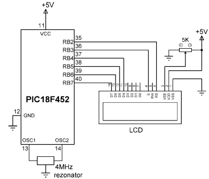
Figure 4.19: Connecting an LCD to a PIC microcontroller
The required program listing is given in Figure 4.20 (program LCD.C). At the beginning of the program PORTB is configured as output with the TRISB = 0 statement. The LCD is then initialized, the display is cleared, and the text message “My Computer” is displayed on the LCD.
/*********************************************************************
WRITING TEXT TO AN LCD
======================
A text based LCD is connected to a PIC microcontroller in the default mode.
This program displays the text "My Computer" on the LCD.
Programmer: Dogan Ibrahim
File: LCD.C
Date: May, 2007
***********************************************************************/
void main() {
TRISB = 0; // Configure PORTB as output
Lcd_Init(PORTB); // Initialize the LCD
Lcd_Cmd(LCD_CLEAR); // Clear the LCD
Lcd_Out(1, 4, "My Computer"); // Display text on LCD
}

Figure 4.20: LCD program listing
4.3.3 Software UART Library
Universal asynchronous receiver transmitter (UART) software library is used for RS232-based serial communication between two electronic devices. In serial communication, only two cables (plus a ground cable) are required to transfer data in either direction. Data is sent in serial format over the cable bit by bit. Normally, the receiving device is in idle mode with its transmit (TX) pin at logic 1, also known as MARK. Data transmission starts when this pin goes to logic 0, also known as SPACE. The first bit sent is the start bit at logic 0. Following this bit, 7 or 8 data bits are sent, followed by an optional parity bit. The last bit sent is the stop bit at logic 1. Serial data is usually sent as a 10-bit frame consisting of a start bit, 8 data bits, and a stop bit, and no parity bits. Figure 4.21 shows how character “A” can be sent using serial communication. Character “A” has the ASCII bit pattern 01000001. As shown in the figure, first the start bit is sent, this is followed by 8 data bits 01000001, and finally the stop bit is sent.
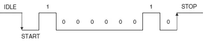
Figure 4.21: Sending character “A” in serial communication
The bit timing is very important in serial communication, and the transmitting (TX) and receiving (RX) devices must have the same bit timings. The bit timing is measured by the baud rate, which specifies the number of bits transmitted or received each second. Typical baud rates are 4800, 9600, 19200, 38400, and so on. For example, when operating at 9600 baud rate with a frame size of 10 bits, 960 characters are transmitted or received each second. The timing between bits is then about 104ms.
In RS232-based serial communication the two devices are connected to each other (see Figure 4.22) using either a 25-way connector or a 9-way connector. Normally only the TX, RX, and GND pins are required for communication. The required pins for both types of connectors are given in Table 4.5.
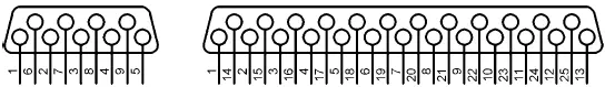
Figure 4.22: 25-way and 9-way RS232 connectors
Table 4.5: Pins required for serial communication
| Pin | 9-way connector | 25-way connector |
|---|---|---|
| TX | 2 | 2 |
| RX | 3 | 3 |
| GND | 5 | 7 |
The voltage levels specified by the RS232 protocol are ±12V. A logic HIGH signal is at –12V and a logic LOW signal is at +12V. PIC microcontrollers, on the other hand, normally operate at 0 to 5V voltage levels, the RS232 signals must be converted to 0 to 5V when input to a microcontroller. Similarly, the output of the microcontroller must be converted to ±12V before sending to the receiving RS232 device. The voltage conversion is usually carried out with RS232 converter chips, such as the MAX232, manufactured by Maxim Inc.
Serial communication may be implemented in hardware using a specific pin of a microcontroller, or the required signals can be generated in software from any required pin of a microcontroller. Hardware implementation requires either an on-chip UART (or USART) circuit or an external UART chip that is connected to the microcontroller. Software-based UART is more commonly used and does not require any special circuits. Serial data is generated by delay loops in software-based UART applications. In this section only the software-based UART functions are described.
The mikroC compiler supports the following software UART functions:
• Soft_Uart_Init
• Soft_Uart_Read
• Soft_Uart_Write
The Soft_Uart_Init function specifies the serial communications parameters and does so in the following order:
port, rx pin, tx pin, baud rate, mode
port is the port used as the software UART (e.g., PORTB), rx is the receive pin number, tx is the transmit pin number, baud rate is the chosen baud rate where the maximum value depends on the clock rate of the microcontroller, and mode specifies whether or not the data should be inverted at the output of the port. A 0 indicates that it should not be inverted, and a 1 indicates that it should be inverted. When an RS232 voltage level converter chip is used (e.g., MAX232) then the mode must be set to 0. Soft_Uart_Init must be the first function called before software-based serial communication is established.
The following example configures the software UART to use PORTB as the serial port, with RB0 as the RX pin and RB1 as the TX pin. The baud rate is set to 9600 with the mode noninverted:
Soft_Uart_Init(PORTB, 0, 1, 9600, 0);
The Soft_Uart_Read function receives a byte from a specified serial port pin. The function returns an error condition and the data is read from the serial port. The function does not wait for data to be available at the port, and therefore the error parameter must be tested if a byte is expected. The error is normally 1 and becomes 0 when a byte is read from the port.
The following example illustrates reading a byte from the serial port configured by calling the function Soft_Uart_Init. The received byte is stored in variable Temp :
do Temp = Soft_Uart_Read(Rx_Error);
while (Rx_Error);
The Soft_Uart_Write function transmits a byte to a configured serial port pin. The data to be sent must be specified as a parameter in the call to the function.
For example, to send character “A” to the serial port pin:
char MyData = 'A';
Soft_Uart_Write(MyData);
The following example illustrates the use of software UART functions.
The serial port of a PC (e.g., COM1) is connected to a PIC18F452 microcontroller, and terminal emulation software (e.g., HyperTerminal) is operated on the PC to use the serial port. Pins RB0 and RB1 of the microcontroller are the RX and TX pins respectively. The required baud rate is 9600.
Читать дальшеИнтервал:
Закладка:
Похожие книги на «Advanced PIC Microcontroller Projects in C»
Представляем Вашему вниманию похожие книги на «Advanced PIC Microcontroller Projects in C» списком для выбора. Мы отобрали схожую по названию и смыслу литературу в надежде предоставить читателям больше вариантов отыскать новые, интересные, ещё непрочитанные произведения.


Обсуждение, отзывы о книге «Advanced PIC Microcontroller Projects in C» и просто собственные мнения читателей. Оставьте ваши комментарии, напишите, что Вы думаете о произведении, его смысле или главных героях. Укажите что конкретно понравилось, а что нет, и почему Вы так считаете.