Qing Li - Real-Time Concepts for Embedded Systems
Здесь есть возможность читать онлайн «Qing Li - Real-Time Concepts for Embedded Systems» весь текст электронной книги совершенно бесплатно (целиком полную версию без сокращений). В некоторых случаях можно слушать аудио, скачать через торрент в формате fb2 и присутствует краткое содержание. Город: San Francisco, Год выпуска: 2003, ISBN: 2003, Издательство: CMP books, Жанр: ОС и Сети, на английском языке. Описание произведения, (предисловие) а так же отзывы посетителей доступны на портале библиотеки ЛибКат.
- Название:Real-Time Concepts for Embedded Systems
- Автор:
- Издательство:CMP books
- Жанр:
- Год:2003
- Город:San Francisco
- ISBN:1-57820-124-1
- Рейтинг книги:4 / 5. Голосов: 1
-
Избранное:Добавить в избранное
- Отзывы:
-
Ваша оценка:
Real-Time Concepts for Embedded Systems: краткое содержание, описание и аннотация
Предлагаем к чтению аннотацию, описание, краткое содержание или предисловие (зависит от того, что написал сам автор книги «Real-Time Concepts for Embedded Systems»). Если вы не нашли необходимую информацию о книге — напишите в комментариях, мы постараемся отыскать её.
Delve into the details of real-time programming so you can develop a working knowledge of the common design patterns and program structures of real-time operating systems (RTOS). The objects and services that are a part of most RTOS kernels are described and real-time system design is explored in detail. You learn how to decompose an application into units and how to combine these units with other objects and services to create standard building blocks. A rich set of ready-to-use, embedded design “building blocks” is also supplied to accelerate your development efforts and increase your productivity.
Experienced developers new to embedded systems and engineering or computer science students will both appreciate the careful balance between theory, illustrations, and practical discussions. Hard-won insights and experiences shed new light on application development, common design problems, and solutions in the embedded space. Technical managers active in software design reviews of real-time embedded systems will find this a valuable reference to the design and implementation phases.
Qing Li is a senior architect at Wind River Systems, Inc., and the lead architect of the company’s embedded IPv6 products. Qing holds four patents pending in the embedded kernel and networking protocol design areas. His 12+ years in engineering include expertise as a principal engineer designing and developing protocol stacks and embedded applications for the telecommunications and networks arena. Qing was one of a four-member Silicon Valley startup that designed and developed proprietary algorithms and applications for embedded biometric devices in the security industry.
Caroline Yao has more than 15 years of high tech experience ranging from development, project and product management, product marketing, business development, and strategic alliances. She is co-inventor of a pending patent and recently served as the director of partner solutions for Wind River Systems, Inc. About the Authors
Real-Time Concepts for Embedded Systems — читать онлайн бесплатно полную книгу (весь текст) целиком
Ниже представлен текст книги, разбитый по страницам. Система сохранения места последней прочитанной страницы, позволяет с удобством читать онлайн бесплатно книгу «Real-Time Concepts for Embedded Systems», без необходимости каждый раз заново искать на чём Вы остановились. Поставьте закладку, и сможете в любой момент перейти на страницу, на которой закончили чтение.
Интервал:
Закладка:
All processors handle exceptions in a defined order. Although not every silicon vendor uses the exact same order of exception processing, generally exceptions are handled according to these priorities, as shown in Table 10.2.
Table 10.2: Exception priorities.
| Highest | Asynchronous | Non-maskable |
| ↓ | Synchronous | Precise |
| Synchronous | Imprecise | |
| Lowest | Asynchronous | Maskable |
The highest priority level of exceptions is usually reserved for system resets, other significant events, or errors that warrant the overall system to reset. In many cases, hardware implementations for this exception also cause much, if not all, of the surrounding hardware to reset to a known state and condition. For this reason, this exception is treated as the highest level.
The next two priority levels reflect a set of errors and special execution conditions internal to the processor. A synchronous exception is generated and acknowledged only at certain states of the internal processor cycle. The sources of these errors are rooted in either the instructions or data that is passed along to be processed.
Typically, the lowest priority is an asynchronous exception external to the core processor. External interrupts (except NMIs) are the only exceptions that can be disabled by software.
From an application point of view, all exceptions have processing priority over operating system objects, including tasks, queues, and semaphores. Figure 10.2 illustrates a general priority framework observed in most embedded computing architectures.
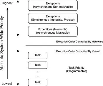
Figure 10.2: System-wide priority scheme.
10.5 Processing General Exceptions
Having introduced the fundamentals of exceptions and external interrupts, it is time to discuss processing exceptions and external interrupts. The overall exception handling mechanism is similar to the mechanism for interrupt handling. In a simplified view, the processor takes the following steps when an exception or an external interrupt is raised:
· Save the current processor state information.
· Load the exception or interrupt handling function into the program counter.
· Transfer control to the handler function and begin execution.
· Restore the processor state information after the handler function completes.
· Return from the exception or interrupt and resume previous execution.
A typical handler function does the following:
· Switch to an exception frame or an interrupt stack.
· Save additional processor state information.
· Mask the current interrupt level but allow higher priority interrupts to occur.
· Perform a minimum amount of work so that a dedicated task can complete the main processing.
10.5.1 Installing Exception Handlers
Exception service routines (ESRs) and interrupt service routines (ISRs) must be installed into the system before exceptions and interrupts can be handled. The installation of an ESR or ISR requires knowledge of the exception and interrupt table (called the general exception table ).
The general exception table, as exemplified in Table 10.1, has a vector address column, which is sometimes also called the vector table . Each vector address points to the beginning of an ESR or ISR. Installing an ESR or ISR requires replacing the appropriate vector table entry with the address of the desired ESR or ISR.
The embedded system startup code typically installs the ESRs at the time of system initialization. Hardware device drivers typically install the appropriate ISRs at the time of driver initialization.
If either an exception or an interrupt occurs when no associated handler function is installed, the system suffers a system fault and may halt. To prevent this problem, it is common for an embedded RTOS to install default handler functions (i.e., functions that perform small amounts of work to ensure the proper reception of and the proper return from exceptions) into the vector table for every possible exception and interrupt in the system. Many RTOSes provide a mechanism that the embedded systems programmer can use to overwrite the default handler function with his or her own or to allow the programmer to insert further processing in addition to the default actions. If allowed, the embedded systems programmer can code specific actions before and after the default action is completed.
In this book, the general term service routine means either an ESR or an ISR when the distinction is not important.
10.5.2 Saving Processor States
When an exception or interrupt comes into context and before invoking the service routine, the processor must perform a set of operations to ensure a proper return of program execution after the service routine is complete. Just as tasks save information in task control blocks, exception and interrupt service routines also need to store blocks of information, called processor state information , somewhere in memory. The processor typically saves a minimum amount of its state information, including the status register (SR) that contains the current processor execution status bits and the program counter (PC) that contains the returning address, which is the instruction to resume execution after the exception. The ESR or the ISR, however, must do more to preserve more complete state information in order to properly resume the program execution that the exception preempted. A later section discusses this issue in more detail.
So, whose stack is used during the exception and interrupt processing?
Stacks are used for the storage requirement of saving processor state information. In an embedded operating system environment, a stack is a statically reserved block of memory and an active dynamic pointer called a stack pointer, as shown in Figure 10.3. In some embedded architectures, such as Motorola's 68000 microprocessors, two separate stacks-the user stack (USP) and the supervisor stack (SSP)-are used. The USP is used when the processor executes in non-privileged mode. The SSP is used when the processor executes in privileged mode.
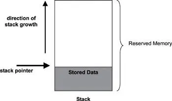
Figure 10.3: Store processor state information onto stack.
Section 10.3.1, 'Internal Errors and Special Conditions Management' on page 145, discusses processor execution modes. On this type of architecture, the processor consciously selects SSP to store its state information during general exception handling. While some architectures offer special support for stack switching, the balance of this chapter assumes a simple environment with just one run-time stack.
As data is saved on the stack, the stack pointer is incremented to reflect the number of bytes copied onto the stack. This process is often called pushing values on the stack . When values are copied off the stack, the stack pointer is decremented by the equivalent number of bytes copied from the stack. This process is called popping values off the stack . The stack pointer always points to the first valid location in order to store data onto the stack. For purposes of this book, the stack grows up; however, a stack can grow in the opposite direction. Note that a typical stack does not store identifiers for the contents. Stack users are required to push and pop items onto and off the stack in a symmetric order. If this rule is not followed during exception or interrupt processing, unintended results are likely to occur.
Читать дальшеИнтервал:
Закладка:
Похожие книги на «Real-Time Concepts for Embedded Systems»
Представляем Вашему вниманию похожие книги на «Real-Time Concepts for Embedded Systems» списком для выбора. Мы отобрали схожую по названию и смыслу литературу в надежде предоставить читателям больше вариантов отыскать новые, интересные, ещё непрочитанные произведения.


Обсуждение, отзывы о книге «Real-Time Concepts for Embedded Systems» и просто собственные мнения читателей. Оставьте ваши комментарии, напишите, что Вы думаете о произведении, его смысле или главных героях. Укажите что конкретно понравилось, а что нет, и почему Вы так считаете.