Qing Li - Real-Time Concepts for Embedded Systems
Здесь есть возможность читать онлайн «Qing Li - Real-Time Concepts for Embedded Systems» весь текст электронной книги совершенно бесплатно (целиком полную версию без сокращений). В некоторых случаях можно слушать аудио, скачать через торрент в формате fb2 и присутствует краткое содержание. Город: San Francisco, Год выпуска: 2003, ISBN: 2003, Издательство: CMP books, Жанр: ОС и Сети, на английском языке. Описание произведения, (предисловие) а так же отзывы посетителей доступны на портале библиотеки ЛибКат.
- Название:Real-Time Concepts for Embedded Systems
- Автор:
- Издательство:CMP books
- Жанр:
- Год:2003
- Город:San Francisco
- ISBN:1-57820-124-1
- Рейтинг книги:4 / 5. Голосов: 1
-
Избранное:Добавить в избранное
- Отзывы:
-
Ваша оценка:
Real-Time Concepts for Embedded Systems: краткое содержание, описание и аннотация
Предлагаем к чтению аннотацию, описание, краткое содержание или предисловие (зависит от того, что написал сам автор книги «Real-Time Concepts for Embedded Systems»). Если вы не нашли необходимую информацию о книге — напишите в комментариях, мы постараемся отыскать её.
Delve into the details of real-time programming so you can develop a working knowledge of the common design patterns and program structures of real-time operating systems (RTOS). The objects and services that are a part of most RTOS kernels are described and real-time system design is explored in detail. You learn how to decompose an application into units and how to combine these units with other objects and services to create standard building blocks. A rich set of ready-to-use, embedded design “building blocks” is also supplied to accelerate your development efforts and increase your productivity.
Experienced developers new to embedded systems and engineering or computer science students will both appreciate the careful balance between theory, illustrations, and practical discussions. Hard-won insights and experiences shed new light on application development, common design problems, and solutions in the embedded space. Technical managers active in software design reviews of real-time embedded systems will find this a valuable reference to the design and implementation phases.
Qing Li is a senior architect at Wind River Systems, Inc., and the lead architect of the company’s embedded IPv6 products. Qing holds four patents pending in the embedded kernel and networking protocol design areas. His 12+ years in engineering include expertise as a principal engineer designing and developing protocol stacks and embedded applications for the telecommunications and networks arena. Qing was one of a four-member Silicon Valley startup that designed and developed proprietary algorithms and applications for embedded biometric devices in the security industry.
Caroline Yao has more than 15 years of high tech experience ranging from development, project and product management, product marketing, business development, and strategic alliances. She is co-inventor of a pending patent and recently served as the director of partner solutions for Wind River Systems, Inc. About the Authors
Real-Time Concepts for Embedded Systems — читать онлайн бесплатно полную книгу (весь текст) целиком
Ниже представлен текст книги, разбитый по страницам. Система сохранения места последней прочитанной страницы, позволяет с удобством читать онлайн бесплатно книгу «Real-Time Concepts for Embedded Systems», без необходимости каждый раз заново искать на чём Вы остановились. Поставьте закладку, и сможете в любой момент перейти на страницу, на которой закончили чтение.
Интервал:
Закладка:
Similarly, another benefit of running the loader out of the ROM is to prevent a program that is behaving badly from corrupting its code in systems without protection from the MMU.
In this example, the loader image is in an executable machine code format. The application image is in the ELF format but has been compressed through an algorithm that works independently of the object file format. The application image is in the ELF format so that the loader can be written as a generic utility, able to load many application program images. If the application image is in the ELF format, the loader program can extract the necessary information from the image for initialization.
3.3.3 Executing from RAM after Image Transfer from Host
In the third boot scenario, the target debug agent transfers an application image from the host system into RAM for execution. This practice is typical during the later development phases when the majority of the device drivers have been fully implemented and debugged. The system can handle interrupts and exceptions correctly. At this stage, the target system facilitates a stable environment for further application development, allowing the embedded developer to focus on application design and implementation rather than the low-level hardware details.
The debug agent is RTOS-aware and understands RTOS objects and services. The debug agent can communicate with a host debugger and transfer target images through the host debugger. The debug agent can also function as a standalone monitor. The developer can access the command line interface for the target debug agent through a simple terminal program over the serial link. The developer can issue commands over the command line interface to instruct the debug agent on the target image’s location on the host system and to initiate the transfer.
The debug agent downloads the image into a temporary area in RAM first. After the download is complete and the image integrity verified, the debug agent initializes the image according to the information presented in the program section header table. This boot scenario is shown in Figure 3.5.
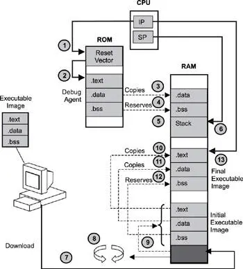
Figure 3.5: Boot sequence for an image executing from RAM after transfer from the host system.
The first six steps are identical to the initial boot scenario. After completing those steps, the process continues as follows:
7. The application image is downloaded from the host development system.
8. The image integrity is verified.
9. The image is decompressed if necessary.
10-12. The debug agent loads the image sections into their respective run addresses in RAM.
13. The debug agent transfers control to the download image.
There is a good reason why the memory area used by the debug agent is not recycled. In this example, the downloaded image contains an RTOS, which is introduced in Chapter 4. One of the core components of a RTOS is a scheduler, which facilitates the simultaneous existence and execution of multiple programs, called tasks or threads. The scheduler can save the execution state information of the debug agent and revive the agent later. Thus, the debug agent can continue to communicate with the host debugger while the downloaded image executes, providing interactive, visual, source-level debugging.
3.4 Target System Software Initialization Sequence
The target image referred to repeatedly in the last section is a combination of sophisticated software components and modules as shown in Figure 3.6. The software components include the following: the board support package (BSP), which contains a full spectrum of drivers for the system hardware components and devices; the RTOS, which provides basic services, such as resource synchronization services, I/O services, and scheduling services needed by the embedded applications; and the other components, which provide additional services, such as file system services and network services.
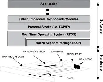
Figure 3.6: Software components of a target image.
These software components perform full system initialization after the target image gains control from the loading program.
Assuming the target image is structured as shown in Figure 3.6, then Figure 3.7 illustrates the steps required to initialize most target systems. The main stages are
· hardware initialization,
· RTOS initialization, and
· application initialization.
Note that these steps are not all that are required to initialize the target system. Rather, this summary provides a high-level example from which to learn. Each stage is discussed more thoroughly in the following sections.
3.4.1 Hardware Initialization
The previous sections described aspects of steps 1 and 2 in Figure 3.7 in which a boot image executes after the CPU begins executing instructions from the reset vector. Typically at this stage, the minimum hardware initialization required to get the boot image to execute is performed, which includes:
1. starting execution at the reset vector
2. putting the processor into a known state by setting the appropriate registers:
○ getting the processor type
○ getting or setting the CPU’s clock speed
3. disabling interrupts and caches
4. initializing memory controller, memory chips, and cache units:
○ getting the start addresses for memory
○ getting the size of memory
○ performing preliminary memory tests, if required
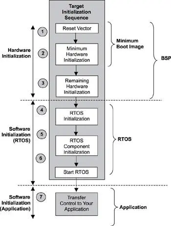
Figure 3.7: The software initialization process.
After the boot sequence initializes the CPU and memory, the boot sequence copies and decompresses, if necessary, the sections of code that need to run. It also copies and decompresses its data into RAM.
Most of the early initialization code is in low-level assembly language that is specific to the target system’s CPU architecture. Later-stage initialization code might be written in a higher-level programming language, such as C.
As the boot code executes, the code calls the appropriate functions to initialize other hardware components, if present, on the target system. Eventually, all devices on the target board are initialized (as shown in step 3 of Figure 3.7). These might include the following:
· setting up execution handlers;
· initializing interrupt handlers;
· initializing bus interfaces, such as VME, PCI, and USB; and
· initializing board peripherals such as serial, LAN, and SCSI.
Most embedded systems developers consider steps 1 and 2 in Figure 3.7 as the initial boot sequence, and steps 1 to 3 as the BSP initialization phase. Steps 1 to 3 are also called the hardware initialization stage.
Writing a BSP for a particular target system is not trivial. The developer must have a good understanding of the underlying hardware components. Along with understanding the target system’s block diagrams, data flow, memory map, and interrupt map, the developer must also know the assembly language for the target system’s microprocessor.
Developers can save a great deal of time and effort by using sample BSPs if they come with the target evaluation board or from the RTOS vendor. Typically, the microprocessor registers that a developer needs to program are listed in these BSPs, along with the sequence in which to work with them to properly initialize target-system hardware.
Читать дальшеИнтервал:
Закладка:
Похожие книги на «Real-Time Concepts for Embedded Systems»
Представляем Вашему вниманию похожие книги на «Real-Time Concepts for Embedded Systems» списком для выбора. Мы отобрали схожую по названию и смыслу литературу в надежде предоставить читателям больше вариантов отыскать новые, интересные, ещё непрочитанные произведения.


Обсуждение, отзывы о книге «Real-Time Concepts for Embedded Systems» и просто собственные мнения читателей. Оставьте ваши комментарии, напишите, что Вы думаете о произведении, его смысле или главных героях. Укажите что конкретно понравилось, а что нет, и почему Вы так считаете.