Liuping Wang - PID Control System Design and Automatic Tuning using MATLAB/Simulink
Здесь есть возможность читать онлайн «Liuping Wang - PID Control System Design and Automatic Tuning using MATLAB/Simulink» — ознакомительный отрывок электронной книги совершенно бесплатно, а после прочтения отрывка купить полную версию. В некоторых случаях можно слушать аудио, скачать через торрент в формате fb2 и присутствует краткое содержание. Жанр: unrecognised, на английском языке. Описание произведения, (предисловие) а так же отзывы посетителей доступны на портале библиотеки ЛибКат.
- Название:PID Control System Design and Automatic Tuning using MATLAB/Simulink
- Автор:
- Жанр:
- Год:неизвестен
- ISBN:нет данных
- Рейтинг книги:3 / 5. Голосов: 1
-
Избранное:Добавить в избранное
- Отзывы:
-
Ваша оценка:
PID Control System Design and Automatic Tuning using MATLAB/Simulink: краткое содержание, описание и аннотация
Предлагаем к чтению аннотацию, описание, краткое содержание или предисловие (зависит от того, что написал сам автор книги «PID Control System Design and Automatic Tuning using MATLAB/Simulink»). Если вы не нашли необходимую информацию о книге — напишите в комментариях, мы постараемся отыскать её.
PID Control System Design and Automatic Tuning using MATLAB Provides unique coverage of PID Control of unmanned aerial vehicles (UAVs), including mathematical models of multi-rotor UAVs, control strategies of UAVs, and automatic tuning of PID controllers for UAVs
Provides detailed descriptions of automatic tuning of PID control systems, including relay feedback control systems, frequency response estimation, Monte-Carlo simulation studies, PID controller design using frequency domain information, and MATLAB/Simulink simulation and implementation programs for automatic tuning Includes 15 MATLAB/Simulink tutorials, in a step-by-step manner, to illustrate the design, simulation, implementation and automatic tuning of PID control systems Assists lecturers, teaching assistants, students, and other readers to learn PID control with constraints and apply the control theory to various areas. Accompanying website includes lecture slides and MATLAB/ Simulink programs
is intended for undergraduate electrical, chemical, mechanical, and aerospace engineering students, and will greatly benefit postgraduate students, researchers, and industrial personnel who work with control systems and their applications.
PID Control System Design and Automatic Tuning using MATLAB/Simulink — читать онлайн ознакомительный отрывок
Ниже представлен текст книги, разбитый по страницам. Система сохранения места последней прочитанной страницы, позволяет с удобством читать онлайн бесплатно книгу «PID Control System Design and Automatic Tuning using MATLAB/Simulink», без необходимости каждый раз заново искать на чём Вы остановились. Поставьте закладку, и сможете в любой момент перейти на страницу, на которой закончили чтение.
Интервал:
Закладка:
With sampling interval (s), the closed-loop step responses are compared in Figure 1.19, where the IP controller structure is used to reduce overshoot to the step reference signal. It is clearly seen that the closed-loop system with is stable; however, with it is not.
Now, we evaluate the closed-loop performance for a PID controller with filter, where the filter time constant is chosen to be . Based on Table 1.5, the PID controller parameters are calculated as for , , , , and for , , , .
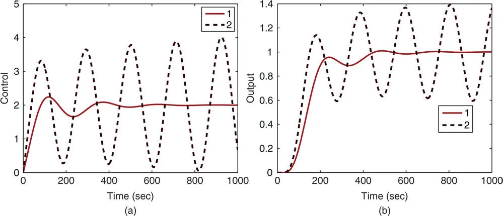
Figure 1.19Comparison of closed-loop responses using Padula and Visioli PI controller ( Example 1.8). (a) Control signal. (b) Output. Key: line (1) tuning rule with  ; line (2) tuning rule with
  .
.

Figure 1.20Comparison of closed-loop responses using Padula and Visioli PID controller ( Example 1.8). (a) Control signal. (b) Output. Key: line (1) tuning rule with  ; line (2) tuning rule with
  .
.
With the same sampling interval , and both proportional and derivative control on output only (IPD structure) where the derivative filter time constant is selected as , the closed-loop responses are simulated. Figure 1.20 compares the closed-loop responses. Both tuning rules lead to stable closed-loop control systems. It is seen that there are overshoots in both reference responses, which was caused by the quite large derivative gains.
1.5.2 Fired Heater Control Example
A fired heater using gas fuel is a heating furnace that is typically used for household heating in the winter times. In this case study, the input to the heating furnace is the feed rate of the gas fuel and the output is the heater outlet or the room temperature in a house. Because the temperature sensors are located away from the heating source, there is a time delay in the measured temperature when the input feed rate changes. Additionally, depending on the operating conditions of the input feed rate, the dynamic response of the temperature is different. Two transfer function models are given in Ralhan and Badgwell (2000) to describe the operations of a gas fired heater at a low fuel operation and a high fuel operation. At the low fuel operating condition, the transfer function is described as
(1.58) 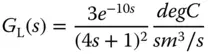
and at the high fuel operating condition,
(1.59) 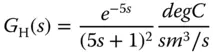
where the time constant is in minutes. Note that there are dramatically differences in time delay and the steady-state gain of the transfer function models.
In this study, we will introduce the effect of input disturbance in the closed-loop simulation by adding a step signal with negative magnitude to the control signal. This input disturbance represents a sudden change in the process that causes the output temperature drop. The effect of this disturbance is further discussed in Chapter 2.
Example 1.9
In this example, we will show how to use the tuning rules to find the PID controller parameters for the fired heater at the lower operating condition using the transfer function (1.58) and simulate the closed-loop response with a step reference signal using sampling interval (min) and a negative step disturbance entering at the half of the simulation time.
The higher operating condition case is left as an exercise.
Solution. Figure 1.21 shows the unit step response with the lines drawn to identify the time delay and time constant for a first order approximation. From the graph, the time delay is found as 9.54 min and the time constant min. With the steady-state gain equal to 3, the approximation using first order plus model leads to the following transfer function:
(1.60) 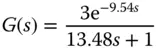
Now, applying the Ziegler–Nichols tuning rules (see Table 1.2), Cohen–Coon tuning rules (see Table 1.3) and Wang–Cluett tuning rules (see Table 1.6), we obtain the PI controller parameters for the fired heater process shown in Table 1.9. The PI controller parameters obtained are drastically different. The PI controllers using Ziegler–Nichols and Wang–Cluett tuning rules produce stable closed-loop system for the fired heater process, however the PI controller using Cohen–Coon tuning rules does not lead to a stable closed-loop system, which was verified using closed-loop simulation. To evaluate the closed-loop control performance, a unit step input signal is used as a reference and a step input disturbance with magnitude of is added to the closed-loop simulation at half of the simulation time. Figure 1.22(a) shows the control signals generated by the PI controllers and Figure 1.22(b) shows the output responses to the reference change and the disturbance signal. Both closed-loop systems have oscillations, but in comparison, the controller using Wang–Cluett tuning rules leads to a slightly better closed-loop performance with less oscillations.
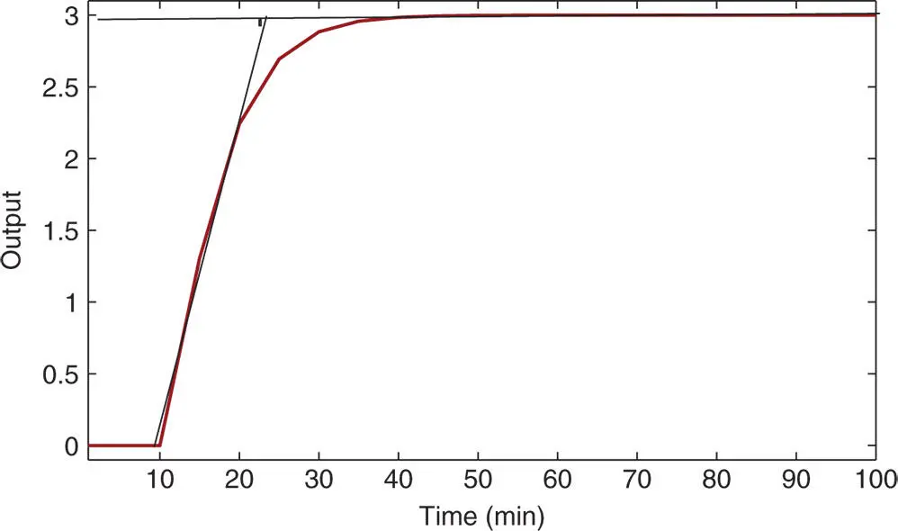
Figure 1.21Unit step response of the fired heater process.
Table 1.9PI controller parameters with reaction curve.
 |
 |
|||
| Ziegler–Nichols | 0.4239 | 28.6200 | ||
| Cohen–Coon | 0.4517 | 13.2353 | ||
| Wang–Cluett | 0.2835 | 15.7610 |
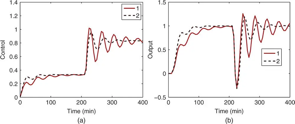
Figure 1.22Comparison of closed-loop responses using Ziegler–Nichols and Wang–Cluett tuning rules ( Example 1.9). (a) Control signal. (b) Output. Key: line (1) Ziegler–Nichols tuning rule; line (2) Wang–Cluett tuning rule.
Читать дальшеИнтервал:
Закладка:
Похожие книги на «PID Control System Design and Automatic Tuning using MATLAB/Simulink»
Представляем Вашему вниманию похожие книги на «PID Control System Design and Automatic Tuning using MATLAB/Simulink» списком для выбора. Мы отобрали схожую по названию и смыслу литературу в надежде предоставить читателям больше вариантов отыскать новые, интересные, ещё непрочитанные произведения.


Обсуждение, отзывы о книге «PID Control System Design and Automatic Tuning using MATLAB/Simulink» и просто собственные мнения читателей. Оставьте ваши комментарии, напишите, что Вы думаете о произведении, его смысле или главных героях. Укажите что конкретно понравилось, а что нет, и почему Вы так считаете.