Liuping Wang - PID Control System Design and Automatic Tuning using MATLAB/Simulink
Здесь есть возможность читать онлайн «Liuping Wang - PID Control System Design and Automatic Tuning using MATLAB/Simulink» — ознакомительный отрывок электронной книги совершенно бесплатно, а после прочтения отрывка купить полную версию. В некоторых случаях можно слушать аудио, скачать через торрент в формате fb2 и присутствует краткое содержание. Жанр: unrecognised, на английском языке. Описание произведения, (предисловие) а так же отзывы посетителей доступны на портале библиотеки ЛибКат.
- Название:PID Control System Design and Automatic Tuning using MATLAB/Simulink
- Автор:
- Жанр:
- Год:неизвестен
- ISBN:нет данных
- Рейтинг книги:3 / 5. Голосов: 1
-
Избранное:Добавить в избранное
- Отзывы:
-
Ваша оценка:
PID Control System Design and Automatic Tuning using MATLAB/Simulink: краткое содержание, описание и аннотация
Предлагаем к чтению аннотацию, описание, краткое содержание или предисловие (зависит от того, что написал сам автор книги «PID Control System Design and Automatic Tuning using MATLAB/Simulink»). Если вы не нашли необходимую информацию о книге — напишите в комментариях, мы постараемся отыскать её.
PID Control System Design and Automatic Tuning using MATLAB Provides unique coverage of PID Control of unmanned aerial vehicles (UAVs), including mathematical models of multi-rotor UAVs, control strategies of UAVs, and automatic tuning of PID controllers for UAVs
Provides detailed descriptions of automatic tuning of PID control systems, including relay feedback control systems, frequency response estimation, Monte-Carlo simulation studies, PID controller design using frequency domain information, and MATLAB/Simulink simulation and implementation programs for automatic tuning Includes 15 MATLAB/Simulink tutorials, in a step-by-step manner, to illustrate the design, simulation, implementation and automatic tuning of PID control systems Assists lecturers, teaching assistants, students, and other readers to learn PID control with constraints and apply the control theory to various areas. Accompanying website includes lecture slides and MATLAB/ Simulink programs
is intended for undergraduate electrical, chemical, mechanical, and aerospace engineering students, and will greatly benefit postgraduate students, researchers, and industrial personnel who work with control systems and their applications.
PID Control System Design and Automatic Tuning using MATLAB/Simulink — читать онлайн ознакомительный отрывок
Ниже представлен текст книги, разбитый по страницам. Система сохранения места последней прочитанной страницы, позволяет с удобством читать онлайн бесплатно книгу «PID Control System Design and Automatic Tuning using MATLAB/Simulink», без необходимости каждый раз заново искать на чём Вы остановились. Поставьте закладку, и сможете в любой момент перейти на страницу, на которой закончили чтение.
Интервал:
Закладка:
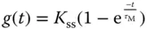
The plant information obtained from the test includes the steady-state gain, defined as
(1.45) 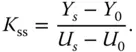
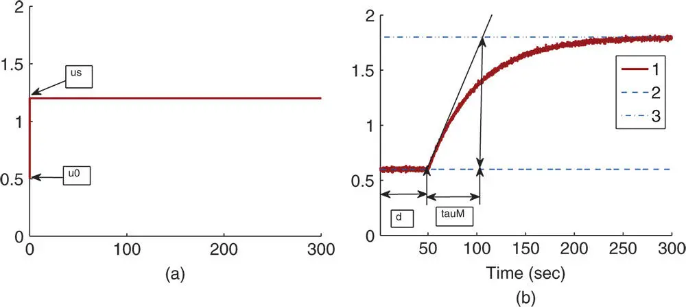
Figure 1.14 Step response data. (a) Input signal. (b) Output signal. Key: line (1) the output response; line (2) steady-state output position before the response (  ); line (3) steady-state output position in completion of the response (
  ).
).
The time delay  is shown in the figure, which is the delayed time when the output responds to the change in the input signal. The parameter time delay
  reflects the situation that the output response remains unchanged despite the step input signal being injected. Thus, it is estimated using the time difference between when the step reference change occurred (
  for this figure) and when the output response moved away from its steady-state value (see the time interval in Figure 1.14(b) marked with the first set of arrows). A line with maximum slope is drawn on Figure 1.14(b), which is intersected with the line corresponding to the indicator of
  . The intersecting point shown in Figure 1.14(b) determines the value of
  that is a measurement of the dynamic response time.
Alternatively, because the step response of a first order system ( 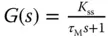 ) to a unit step input signal can be expressed as
and when the variable time  ,
,

thus, we can determine the time constant  using 63.2% of the rising time in the step response. This estimation of time constant gives a different value from the case when using the maximum slope approach. For the majority of the applications, this will result in a smaller time constant
  , and from the empirical tuning rules stated in the later part of the section, a smaller proportional gain
  will follow. One can evaluate this approach as an exercise using Problem 1.2.
Essentially, the step response test gives the parameters in the first order plus delay description of the process as in (1.44).
There is a second set of Ziegler–Nichols tuning rules that is based on the plant step response test data. This is also called the Ziegler–Nichols tuning rules using reaction curve. With these parameters, Ziegler–Nichols tuning rules using a reaction curve are given in Table 1.2. By the nature of this testing procedure (open-loop testing), the tuning rules should apply to stable systems.
Table 1.2 Ziegler-Nichols tuning rules with a reaction curve.
 |
 |
 |
||||
| P |  |
|||||
| PI |  |
 |
||||
| PID |  |
 |
 |
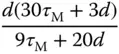
Table 1.3 Cohen–Coon tuning rules with a reaction curve.
 |
 |
 |
||||
| P | 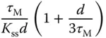 |
|||||
| PI | 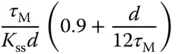 |
 |
||||
| PID | 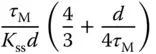 |
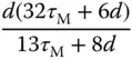 |
 |
There is another set of tuning rules that are derived based on the reaction curve, termed Cohen and Coon tuning rules. Table 1.3gives the PID controller parameters calculated from Cohen and Coon tuning rules.
Читать дальшеИнтервал:
Закладка:
Похожие книги на «PID Control System Design and Automatic Tuning using MATLAB/Simulink»
Представляем Вашему вниманию похожие книги на «PID Control System Design and Automatic Tuning using MATLAB/Simulink» списком для выбора. Мы отобрали схожую по названию и смыслу литературу в надежде предоставить читателям больше вариантов отыскать новые, интересные, ещё непрочитанные произведения.


Обсуждение, отзывы о книге «PID Control System Design and Automatic Tuning using MATLAB/Simulink» и просто собственные мнения читателей. Оставьте ваши комментарии, напишите, что Вы думаете о произведении, его смысле или главных героях. Укажите что конкретно понравилось, а что нет, и почему Вы так считаете.