Marvin Rausand - Risk Assessment
Здесь есть возможность читать онлайн «Marvin Rausand - Risk Assessment» — ознакомительный отрывок электронной книги совершенно бесплатно, а после прочтения отрывка купить полную версию. В некоторых случаях можно слушать аудио, скачать через торрент в формате fb2 и присутствует краткое содержание. Жанр: unrecognised, на английском языке. Описание произведения, (предисловие) а так же отзывы посетителей доступны на портале библиотеки ЛибКат.
- Название:Risk Assessment
- Автор:
- Жанр:
- Год:неизвестен
- ISBN:нет данных
- Рейтинг книги:3 / 5. Голосов: 1
-
Избранное:Добавить в избранное
- Отзывы:
-
Ваша оценка:
Risk Assessment: краткое содержание, описание и аннотация
Предлагаем к чтению аннотацию, описание, краткое содержание или предисловие (зависит от того, что написал сам автор книги «Risk Assessment»). Если вы не нашли необходимую информацию о книге — напишите в комментариях, мы постараемся отыскать её.
2nd Edition
The book begins with an introduction of risk analysis, assessment, and management, and includes a new section on the history of risk analysis. It covers hazards and threats, how to measure and evaluate risk, and risk management. It also adds new sections on risk governance and risk-informed decision making; combining accident theories and criteria for evaluating data sources; and subjective probabilities. The risk assessment process is covered, as are how to establish context; planning and preparing; and identification, analysis, and evaluation of risk.
also offers new coverage of safe job analysis and semi-quantitative methods, and it discusses barrier management and HRA methods for offshore application. Finally, it looks at dynamic risk analysis, security and life-cycle use of risk.
Serves as a practical and modern guide to the current applications of risk analysis and assessment, supports key standards, and supplements legislation related to risk analysis Updated and revised to align with ISO 31000 Risk Management and other new standards and includes new chapters on security, dynamic risk analysis, as well as life-cycle use of risk analysis Provides in-depth coverage on hazard identification, methodologically outlining the steps for use of checklists, conducting preliminary hazard analysis, and job safety analysis Presents new coverage on the history of risk analysis, criteria for evaluating data sources, risk-informed decision making, subjective probabilities, semi-quantitative methods, and barrier management Contains more applications and examples, new and revised problems throughout, and detailed appendices that outline key terms and acronyms Supplemented with a book companion website containing Solutions to problems, presentation material and an Instructor Manual
is ideal for courses on risk analysis/risk assessment and systems engineering at the upper-undergraduate and graduate levels. It is also an excellent reference and resource for engineers, researchers, consultants, and practitioners who carry out risk assessment techniques in their everyday work.
Risk Assessment — читать онлайн ознакомительный отрывок
Ниже представлен текст книги, разбитый по страницам. Система сохранения места последней прочитанной страницы, позволяет с удобством читать онлайн бесплатно книгу «Risk Assessment», без необходимости каждый раз заново искать на чём Вы остановились. Поставьте закладку, и сможете в любой момент перейти на страницу, на которой закончили чтение.
Интервал:
Закладка:
A technical system is a system made of mechanical, electrical, electronic, and/or programmable electronic hardware components, and – more and more often – software. Technical systems are designed, built, and operated by people.
4.2.2 Sociotechnical System
The term “sociotechnical system” was coined by the Tavistock Institute in London at the end of the 1950s, based on the general system theory developed by Ludwig von Bertalanffy in 1949 (e.g. see von Bertalanffy 1968). We consider a sociotechnical system a special type of systems and simply use the definition:
Definition 4.2 (Sociotechnical system)
A system that consists of technical, human, and organizational elements.
A sociotechnical system may be regarded as two interrelated subsystems: (i) a technical system comprising hardware and software and (ii) a social system with humans and organization. Sociotechnical systems are usually governed by organizational policies and rules.
Remark 4.1 (Sociotechnical systems treated as technical systems)
Many of the study objects that are subject to risk assessment are in reality sociotechnical systems, but are far too often treated as pure technical systems without any attempt to model the human and in particular the organizational elements of the systems.
4.2.3 Deterministic Versus Non‐Deterministic System
A deterministic system may be defined as follows:
Definition 4.3 (Deterministic system)
A system where a given sequence of inputs will always produce the same sequence of outputs.
A typical example of a deterministic system is a pure software system. Each time you enter a specific sequence of commands, you get the same response or output from the software system. Technical systems are generally nondeterministic , because the system components may deteriorate and fail. Social systems are also nondeterministic because the system's behavior is partly dependent on human operators who may commit errors. Sociotechnical systems are hence nondeterministic.
4.2.4 System Breakdown Structure
The system breakdown structure was introduced briefly in Chapter 3as part of step 2.1 of the risk assessment process. The system elements (i.e. subsystems, subsubsystems, and so on, down to the component level) may be organized as a system breakdown structure as shown in Figure 4.1, where the system is split into three levels. The levels of the hierarchy are called indenture levels , where the first level is called indenture level 1, the next, indenture level 2, and so on. IEV defines indenture level as the “level of subdivision within a system hierarchy” (IEV 192‐01‐05). The number of levels required depends on the size of the system and the objectives of the risk assessment. The various subsystems may have different numbers of levels.
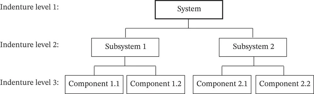 Figure 4.1System breakdown structure (simplified).
Figure 4.1shows a breakdown structure where the physical system is broken down into subsystems and components. An alternative approach is to consider the system functions and to break each function down into subfunctions and actions. A functional breakdown structure may often be more useful than a hardware breakdown structure as a starting point for risk and reliability studies.
The causal structure for a system failure or a system accident may also be represented as a hierarchical structure starting from the system failure/accident. Indenture level 2 represents the direct causes of the failure/accident, whereas indenture level 3 represents the direct causes leading to each of the causes at indenture level 2, and so on. The obtained structure represents a hierarchical structure of the causes of the system failure/accident.
4.2.5 System Boundary
A risk assessment is always based on a number of assumptions and boundary conditions. The most notable is the system boundary that specifies which parts of the system that are included in the study object and which parts are not. All systems are used in some sort of environment that may influence and be influenced by the system. To delimit the study object, a system boundary is established to define what is inside and what is outside of the system. The inputs to and outputs from the study object are drawn up, as shown in Figure 4.2. The system boundary may be defined as follows:
Definition 4.4 (System boundary)
The system boundary separates the internal components and processes of a system from external entities. Internal to its boundary, the system has some degree of integrity, meaning the parts are working together and this integrity gives the system a degree of autonomy. 1
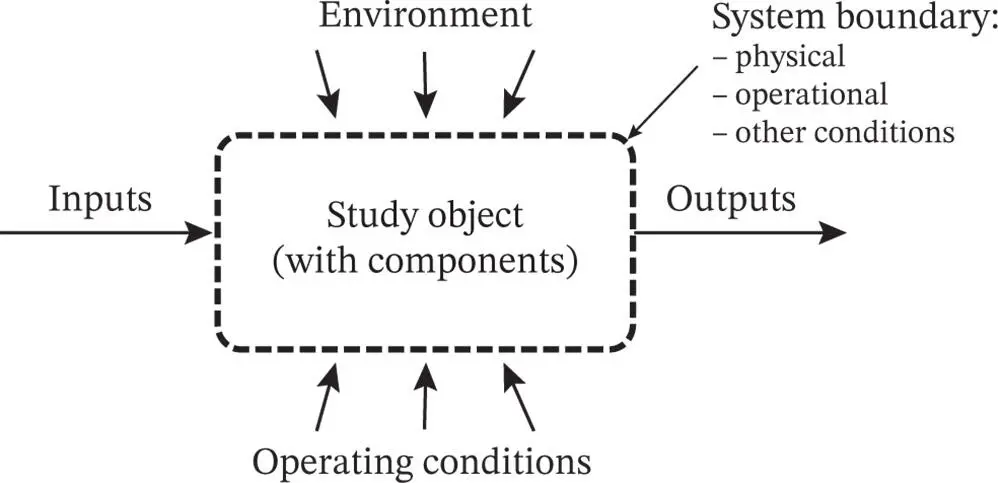 Figure 4.2A system and its boundary.
4.2.6 Assumptions
All assumptions and boundary conditions should be clearly specified in the documentation of the risk analysis. Examples include answers to questions, such as
– What are the objectives of the study?
– What level of detail is required?
– What are the environmental conditions for the system?
– How is the system operated?
– Which operational phases are to be included in the study (e.g. start‐up, steady state, maintenance, and disposal)?
– Which external stresses should be considered (e.g. earthquakes, lightning strikes, sabotage, and cyberattacks)?
Some of these assumptions are also mentioned in Chapter 3.
4.2.7 Closed and Open Systems
The study object may be a closed or an open system. A closed system may be defined as follows:
Definition 4.5 (Closed system)
A system where the interface to the environment is static and always according to the assumptions specified.
In a closed system, the required inputs are always available and random disturbances in the environment that may influence the system are nonexisting. Most of the systems that are considered in this book have a closed boundary. An open system is defined as follows:
Definition 4.6 (Open system)
A system where disturbances in the environment may influence the study object and required system inputs and outputs may fluctuate or even be blocked.
Open systems are generally more difficult to analyze than closed systems.
4.3 Operating Context
Items are generally designed and built for an intended operating context that should be clearly stated in the item specification and in the user documentation.
Definition 4.7 (Operating context)
The environmental and operating conditions under which the item is (or is expected to be) operating.
The operating context specifies how the item is to be operated and maintained, the limits to various operating conditions (e.g. inputs, usage, and loads), and which environmental conditions the item is supposed to work in, as illustrated in Example 4.1
Example 4.1(Operating context for a washing machine)
Consider a domestic washing machine. The user manual of the washing machine may, for example, specify intervals for the voltage and frequency of the power supply, the pressure and temperature of the water supply, the type and weight of laundry (e.g. clothes, carpets) put into the machine, the temperature in the room where the machine is located, and the surface on which the machine is placed. 2
Читать дальшеИнтервал:
Закладка:
Похожие книги на «Risk Assessment»
Представляем Вашему вниманию похожие книги на «Risk Assessment» списком для выбора. Мы отобрали схожую по названию и смыслу литературу в надежде предоставить читателям больше вариантов отыскать новые, интересные, ещё непрочитанные произведения.


Обсуждение, отзывы о книге «Risk Assessment» и просто собственные мнения читателей. Оставьте ваши комментарии, напишите, что Вы думаете о произведении, его смысле или главных героях. Укажите что конкретно понравилось, а что нет, и почему Вы так считаете.