Doruk Senkal - Whole-Angle MEMS Gyroscopes
Здесь есть возможность читать онлайн «Doruk Senkal - Whole-Angle MEMS Gyroscopes» — ознакомительный отрывок электронной книги совершенно бесплатно, а после прочтения отрывка купить полную версию. В некоторых случаях можно слушать аудио, скачать через торрент в формате fb2 и присутствует краткое содержание. Жанр: unrecognised, на английском языке. Описание произведения, (предисловие) а так же отзывы посетителей доступны на портале библиотеки ЛибКат.
- Название:Whole-Angle MEMS Gyroscopes
- Автор:
- Жанр:
- Год:неизвестен
- ISBN:нет данных
- Рейтинг книги:5 / 5. Голосов: 1
-
Избранное:Добавить в избранное
- Отзывы:
-
Ваша оценка:
Whole-Angle MEMS Gyroscopes: краткое содержание, описание и аннотация
Предлагаем к чтению аннотацию, описание, краткое содержание или предисловие (зависит от того, что написал сам автор книги «Whole-Angle MEMS Gyroscopes»). Если вы не нашли необходимую информацию о книге — напишите в комментариях, мы постараемся отыскать её.
Whole-Angle Gyroscopes: Challenges and Opportunities
Whole-Angle Gyroscopes
Whole-Angle MEMS Gyroscopes — читать онлайн ознакомительный отрывок
Ниже представлен текст книги, разбитый по страницам. Система сохранения места последней прочитанной страницы, позволяет с удобством читать онлайн бесплатно книгу «Whole-Angle MEMS Gyroscopes», без необходимости каждый раз заново искать на чём Вы остановились. Поставьте закладку, и сможете в любой момент перейти на страницу, на которой закончили чтение.
Интервал:
Закладка:
1 Introduction
Coriolis Vibratory Gyroscopes (CVGs) are mechanical transducers that detect angular rotation around a particular axis. In its most fundamental form, a CVG consists of two or more mechanically coupled vibratory modes, a forcing system to induce vibratory motion and a sensing system to detect vibratory motion. Angular rotation can be detected by sensing the energy transfer from one vibratory mode to another in the presense of Coriolis forces, Figure 1.1.
Historically, first examples of CVGs can be found in the Aerospace Industry, which were primarily used for navigation and platform stabilization applications. Later, advent of Micro‐electromechanical System (MEMS) fabrication techniques brought along orders of magnitude reduction in cost, size, weight, and power (CSWaP), which made CVGs truly ubiquitous. Today CVGs are used in a wide variety of civilian applications, examples include:
Industrial applications, such as robotics and automation;
Automobile stabilization, traction control, and roll‐over detection;
Gesture recognition and localization in gaming and mobile devices;
Optical image stabilization (OIS) of cameras;
Head tracking in Augmented Reality (AR) and Virtual Reality (VR);
Autonomous vehicles, such as self‐driving cars and Unmanned Aerial Vehicles (UAVs).
1.1 Types of Coriolis Vibratory Gyroscopes
CVGs can be divided into two broad categories based on the gyroscope's mechanical element [1]: degenerate mode (i.e.  ‐axis) gyroscopes, which have
  –
–  symmetry (
  of 0 Hz), and nondegenerate mode gyroscopes, which are designed intentionally to be asymmetric in
  and
and  modes (
  ). Degenerate mode
  ‐axis gyroscopes offer a number of unique advantages compared to nondegenerate vibratory rate gyroscopes, including higher rate sensitivity, ability to implement whole‐angle mechanization with mechanically unlimited dynamic range, exceptional scale factor stability, and a potential for self‐calibration.
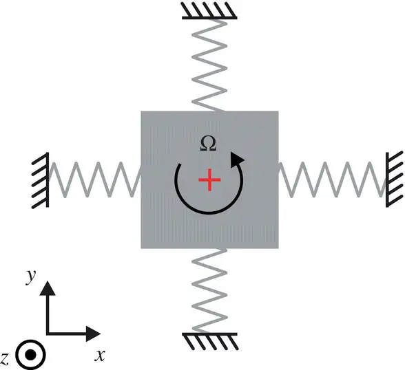
Figure 1.1 Coriolis Vibratory Gyroscopes, in their simplest form, consist of a vibrating element with two or more mechanically coupled vibratory modes. Illustration shows a  ‐axis gyroscope and its vibratory modes along
  ‐ and
‐ and  ‐axis.
1.1.1 Nondegenerate Mode Gyroscopes
Nondegenerate mode CVGs are currently being used in a variety of commercial applications due to ease of fabrication and lower cost. Most common implementations utilize two to four vibratory modes for sensing angular velocity along one to three axes. This is commonly achieved by forcing a proof mass structure into oscillation in a so‐called “drive” mode and sensing the oscillation on one or more “sense” modes. For example, the  ‐axis of the gyroscope in Figure 1.1, can be instrumented as a drive mode and the
  ‐axis can be instrumented as a sense mode. When a nonzero angular velocity is exerted (i.e. along the
  ‐axis in Figure 1.1), the resultant Coriolis force causes the sense mode (i.e. the mode along the
  ‐axis in Figure 1.1) to oscillate at the drive frequency at an amplitude proportional to input angular velocity.
Resonance frequency of sense modes are typically designed to be several hundreds to a few thousand hertzs away from the drive frequency. The existence of this so‐called drive‐sense separation (  ) makes nondegenerate mode gyroscopes robust to fabrication imperfections. However, a trade‐off between bandwidth and transducer sensitivity exists since smaller drive‐sense separation frequency leads to higher transducer sensitivity, while the mechanical bandwidth of the sensor is typically limited by drive‐sense separation (
  ).
).
Nondegenerate mode gyroscopes are typically operated using open‐loop mechanization. In open‐loop mechanization, “drive” mode oscillation is sustained via a positive feedback loop. The amplitidue of “drive” mode oscillations are controlled via the so‐called Amplitude Gain Control (AGC) loop. No feedback loop is employed on the “sense” mode, which leaves “sense” mode proof mass free to oscillate in response to the angular rate input.
1.1.2 Degenerate Mode Gyroscopes
Degenerate mode gyroscopes utilize two symmetric modes for detecting angular rotation. For an ideal degenerate mode gyroscope, these two modes have identical stiffness and damping; for this reason typically an axisymmetric or  –
–  symmetric structure is used, such as a ring, disk, wineglass, etc. Degenerate mode gyroscopes are commonly employed in two primary modes of instrumentation: (i) force‐to‐rebalance (FTR) (rate) mechanization and (ii) whole‐angle mechanization.
In FTR mechanization, an external force is applied to the vibratory element that is equal and opposite to the Coriolis force being generated. This is a rate measuring gyroscope implementation, where the magnitude of externally applied force can be used to detect angular velocity. The main benefit of this mode of operation is to boost the mechanical bandwidth of the resonator, which would otherwise be limited by the close to zero drive‐sense separation (  ) of the degenerate mode gyroscope.
Интервал:
Закладка:
Похожие книги на «Whole-Angle MEMS Gyroscopes»
Представляем Вашему вниманию похожие книги на «Whole-Angle MEMS Gyroscopes» списком для выбора. Мы отобрали схожую по названию и смыслу литературу в надежде предоставить читателям больше вариантов отыскать новые, интересные, ещё непрочитанные произведения.


Обсуждение, отзывы о книге «Whole-Angle MEMS Gyroscopes» и просто собственные мнения читателей. Оставьте ваши комментарии, напишите, что Вы думаете о произведении, его смысле или главных героях. Укажите что конкретно понравилось, а что нет, и почему Вы так считаете.