George F. Elmasry - Dynamic Spectrum Access Decisions
Здесь есть возможность читать онлайн «George F. Elmasry - Dynamic Spectrum Access Decisions» — ознакомительный отрывок электронной книги совершенно бесплатно, а после прочтения отрывка купить полную версию. В некоторых случаях можно слушать аудио, скачать через торрент в формате fb2 и присутствует краткое содержание. Жанр: unrecognised, на английском языке. Описание произведения, (предисловие) а так же отзывы посетителей доступны на портале библиотеки ЛибКат.
- Название:Dynamic Spectrum Access Decisions
- Автор:
- Жанр:
- Год:неизвестен
- ISBN:нет данных
- Рейтинг книги:3 / 5. Голосов: 1
-
Избранное:Добавить в избранное
- Отзывы:
-
Ваша оценка:
Dynamic Spectrum Access Decisions: краткое содержание, описание и аннотация
Предлагаем к чтению аннотацию, описание, краткое содержание или предисловие (зависит от того, что написал сам автор книги «Dynamic Spectrum Access Decisions»). Если вы не нашли необходимую информацию о книге — напишите в комментариях, мы постараемся отыскать её.
dynamic spectrum access approach using the latest applications and techniques
Dynamic Spectrum Access Decisions: Local, Distributed, Centralized and Hybrid Designs Dynamic Spectrum Access Decisions · Licensed spectrum bands
· Unlicensed spectrum bands
· Civilian communications
· Military communications
Consisting of a set of techniques derived from network information theory and game theory, DSA improves the performance of communications networks. This book addresses advanced topics in this area and assumes basic knowledge of wireless communications.
Dynamic Spectrum Access Decisions — читать онлайн ознакомительный отрывок
Ниже представлен текст книги, разбитый по страницам. Система сохранения места последней прочитанной страницы, позволяет с удобством читать онлайн бесплатно книгу «Dynamic Spectrum Access Decisions», без необходимости каждый раз заново искать на чём Вы остановились. Поставьте закладку, и сможете в любой момент перейти на страницу, на которой закончили чтение.
Интервал:
Закладка:
6.2.1 Spatial Modeling and SIR
Spatial modeling in 5G can use a set of metrics that can affect SIR. SIR becomes an instantaneous ratio of desired energy to all the additives of undesired interferences and noise. Thus SIR can be considered a random variable that depends on a set of factors that include the following:
1 The distance between the transmitting node and the receiving node. Much like traditional signals, this factor can be modeled by a path loss model. All path loss models follow an inverse‐power law with an exponent trend. For example, in a free space model, signal power decrease with distance in a quadratic trend. Other path loss models can use different exponent values to model signal scattering and signal absorption.
2 The number of active transmitters in a given proximity. For a given receiver, and during the time of reception, there are different potential combinations of active transmitters where their signal will appear as interference. The sum of interference power from all the transmitting nodes, taking into consideration their distances from the given receiver, has to be modeled. In a dense deployment of 5G cells, this sum of interference power from other transmitters can exceed the noise power threshold that is selected to ensure reliable connectivity.
3 The ambient noise. SIR will be affected by noise power and this noise will depend on the received signal and the interference power. Notably, if a 5G deployment resorts to lower transmission power, the ambient noise impact on SIR can be the larger factor. On the other hand, if a 5G deployment resorts to a high transmission power, the sum of interference power in step 2 above becomes the larger factor.
4 Other factors. There are many other factors that can affect the SIR calculation such as fading and shadowing, transceiver design (e.g., the use of multiple antenna and interference cancelation techniques), and adaptive power control.
A simple representation of SIR at a typical receiving node can be expressed as:
(6.1) 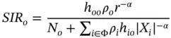
where o represents the origin in the spatial model assuming the receiving node is at the origin of the spatial plan, h iois the fading coefficient of the channel at the receiving node for the signal transmitted from node i , ρ iis the transmit power of transmitter i , N ois the noise power, Φ is the set of all interfering nodes, 7and X iexpresses the distance between the i th interfering node and o .
Notice that Equation (6.1)performs the following:
1 It puts the receiving node at the origin of the spatial model o making the calculation with respect to o.
2 It creates a probabilistic spatial model where transmitting nodes can be randomly positioned with respect to the origin.
3 It consolidates path loss calculation of the subset of transmitting nodes presumed to cause interference with the receiving node at the origin.
Equation (6.1) can be used in a spatial model to calculate SIR, which can be used in a 5G dense deployment to calculate connectivity and coverage when assigning spectrum resources. In addition, SIR calculation can be used to estimate the capacity and throughput of a given deployment area. This calculation can further lead to collecting metrics that can measure the reliability of the 5G networks. 8
6.2.2 SIR and Connectivity
Let us define the metric “connectivity” as the probability that a pair of nodes in a network will be able to exchange information at a specified rate R through a single over‐the‐air hop. There is a threshold β for SIR that can be used in a simple manner to express connectivity where connectivity can be assumed to occur if Pr[ SIR > β ]. That is, if the estimated SIR is less than β , the node pair would decide that a link is not possible. 9The desired rate R can be expressed in bits per second (bps) and can be estimated from β using the Shannon's equation as follows:
(6.2) 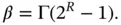
In Equation (6.2), Γ ≥ 1, which represents the collective interference impact on data rate. 10The node pair would calculate SIR from Equation (6.1) and calculate β from Equation (6.2) and decide if single over‐the‐air hop connectivity is possible or not. 11
In 5G, connectivity has many use cases. Consider the following use cases:
1 If there are no other cells using the same frequency in the area (5G can be considered to be operating much like Figure 6.4) and there is a single active end user, the coverage area for a given rate is decided by the SIR estimation in Equation (6.1) and the threshold β in Equation (6.2) is calculated in a straightforward manner. If SIR > β, the end‐user device has to simply refrain from transmitting when receiving to avoid SI in order to maintain the desired data rate.
2 If a source and destination pair have to communicate through one or more relay nodes, a path must be found where all of the over‐the‐air hops satisfy Equations (6.1) and (6.2). When there is a single flow, as shown in Figure 6.5, this estimation is also straightforward provided that interleaving of transmit and receive time is done accurately to prevent SI between all node pairs in the path.
3 When there are more than one flow, all flows have only one over‐the‐air hop, and there is one flow per cell, connectivity calculation will use the summation in Equation (6.1) to consider all transmitting and receiving node pairs. This case is illustrated in Figure 6.6. Here, accurate directionality, power control, and narrowing the beam as much as possible can reduce the effect of SI.
4 The general case when there is more than one flow and flows use relay nodes. With this case, there are different ways to describe network connectivity based on the single over‐the‐air hop connectivity. Reaching full network connectivity means that all communicating pairs and all single over‐the‐air hops meet the conditions in Equations (6.1) and (6.2). 12With this case, interleaving transmit and receive time per each node is not sufficient to avoid interference. Spatial separation becomes more complex and DSM is needed to ensure connectivity. This case is covered in more detail in Section 6.2.3.
Figure 6.5Single flow in a cell area of coverage.
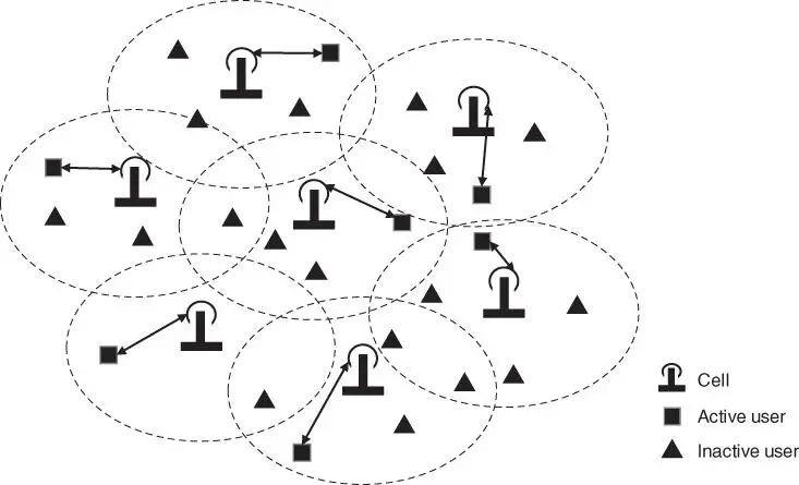
Figure 6.6Multi‐flow, each with a single hop to a different cell.
6.2.3 General Case Connectivity and Coverage
Connectivity and coverage for the 5G general case are multifaceted. This section covers two important aspects of the general case: transmission capacity and cell overlay. There are more aspects of connectivity and coverage and how they relate to DSM in 5G but these two aspects should give the reader the important basis for 5G DSM.
6.2.3.1 Transmission Capacity
The main goal of DSM is to increase the network throughput or transmission capacity in a given area. Given that in 5G we have mobile users and cells that can also be mobile, we can conceptualize a 5G network as an ad hoc wireless network while putting aside the backhaul wired links. The goal here is to create a spatial metric in which throughput is measured as a function of both rate of transmission and the distance between the transmitting and receiving nodes. We not only put aside wired backhaul links, we also put aside the effect of implementation specific techniques such as physical layer algorithms and channel access protocol. The goal here is to create a spatial metric that is generic enough and points to some fundamental properties of the 5G network. The analysis below has the sole goal of pointing to spatial metrics as the problem domain can get complicated if we want to create a comprehensive model.
Читать дальшеИнтервал:
Закладка:
Похожие книги на «Dynamic Spectrum Access Decisions»
Представляем Вашему вниманию похожие книги на «Dynamic Spectrum Access Decisions» списком для выбора. Мы отобрали схожую по названию и смыслу литературу в надежде предоставить читателям больше вариантов отыскать новые, интересные, ещё непрочитанные произведения.


Обсуждение, отзывы о книге «Dynamic Spectrum Access Decisions» и просто собственные мнения читателей. Оставьте ваши комментарии, напишите, что Вы думаете о произведении, его смысле или главных героях. Укажите что конкретно понравилось, а что нет, и почему Вы так считаете.