Saida Helali - Systems and Network Infrastructure Integration
Здесь есть возможность читать онлайн «Saida Helali - Systems and Network Infrastructure Integration» — ознакомительный отрывок электронной книги совершенно бесплатно, а после прочтения отрывка купить полную версию. В некоторых случаях можно слушать аудио, скачать через торрент в формате fb2 и присутствует краткое содержание. Жанр: unrecognised, на английском языке. Описание произведения, (предисловие) а так же отзывы посетителей доступны на портале библиотеки ЛибКат.

- Название:Systems and Network Infrastructure Integration
- Автор:
- Жанр:
- Год:неизвестен
- ISBN:нет данных
- Рейтинг книги:5 / 5. Голосов: 1
-
Избранное:Добавить в избранное
- Отзывы:
-
Ваша оценка:
Systems and Network Infrastructure Integration: краткое содержание, описание и аннотация
Предлагаем к чтению аннотацию, описание, краткое содержание или предисловие (зависит от того, что написал сам автор книги «Systems and Network Infrastructure Integration»). Если вы не нашли необходимую информацию о книге — напишите в комментариях, мы постараемся отыскать её.
Systems and Network Infrastructure Integration — читать онлайн ознакомительный отрывок
Ниже представлен текст книги, разбитый по страницам. Система сохранения места последней прочитанной страницы, позволяет с удобством читать онлайн бесплатно книгу «Systems and Network Infrastructure Integration», без необходимости каждый раз заново искать на чём Вы остановились. Поставьте закладку, и сможете в любой момент перейти на страницу, на которой закончили чтение.
Интервал:
Закладка:
Figure 2.3. Adding IOS Image. For a color version of the figure, see www.iste.co.uk/helali/systems.zip
We select the image file as well as the corresponding platform and model before saving.
A base configuration is saved as a text file (baseconfig.txt) that is automatically created in the specified path. This text file is later used to customize the base configuration of all routers according to the need.
The Cisco 1700 router is added and the following message appears: “Warning: IDLE PC will have to be configured!”
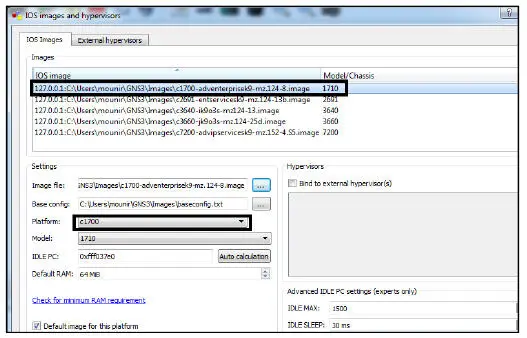
Figure 2.4. Example of a router image. For a color version of the figure, see www.iste.co.uk/helali/systems.zip
IDLE PC
The field “ IDLE PC” is a value that enables the optimization of CPU resource allocation.
GNS3 consumes a very large amount of resources. Without additional configuration, a single router in GNS3 can use 100% of the processor. However, it is possible to reduce this drain on resources by defining an IDLE PC value. To do this, right-click on the router and then click the Start button. Next, right-click again and select IDLE PC.
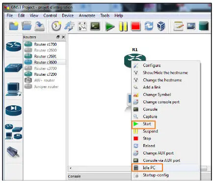
Figure 2.5. Using the IDLE PC function. For a color version of the figure, see www.iste.co.uk/helali/systems.zip
GNS3 calculates the possible values for IDLE PC and offers a range of choices, as shown in Figure 2.6.
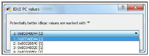
Figure 2.6. Suggested range of IDLE PC values. For a color version of the figure, see www.iste.co.uk/helali/systems.zip
Using the Task Manager, we can test the extent to which applying the suggested IDLE PC value will affect the processor load.
2.3.4.2. Constructing a simple network topology
We begin by selecting a router. Only the types of routers for which we have already provided an IOS image are available; all others are grayed out. In Figure 2.7, we have two router models available (the previously added C1700 and the existing C3600).
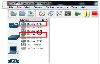
Figure 2.7. Available router images. For a color version of the figure, see www.iste.co.uk/helali/systems.zip
Using Drag & Drop, we drag the desired routers into the main window.
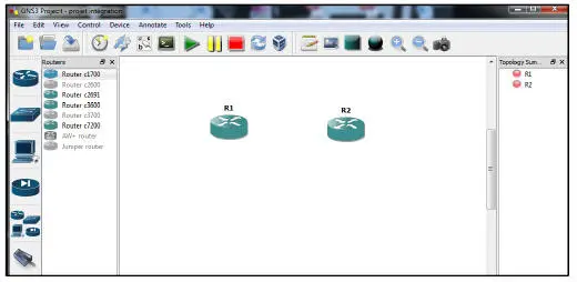
Figure 2.8. Adding routers to a topology. For a color version of the figure, see www.iste.co.uk/helali/systems.zip
To configure a router, right-click and select CONFIGURE.
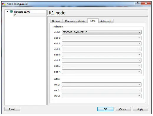
Figure 2.9. Configuration of a router. For a color version of the figure, see www.iste.co.uk/helali/systems.zip
Memory values can be adjusted here and, depending on the type, different modular locations can also be added.
GNS3 offers a selection of modules that can be virtually installed in routers.
To connect the two routers, simply select the type of corresponding connection using the left-hand button (a serial connection in this case) and click on the respective routers on the left to select the desired interface.
A corresponding connection line appears at R1, which is then dragged toward the partner router R2.
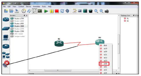
Figure 2.10. Connection of two routers. For a color version of the figure, see www.iste.co.uk/helali/systems.zip
Although switches cannot be emulated, it is still possible to simulate them. A corresponding button to the left allows you to select the desired switch. This is usually an Ethernet switch.
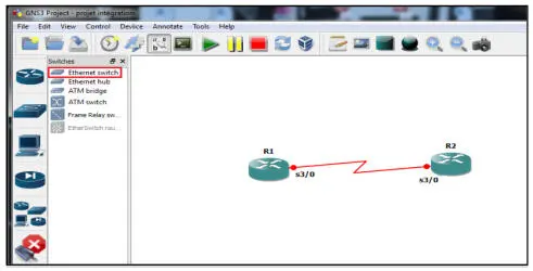
Figure 2.11. Adding a switch. For a color version of the figure, see www.iste.co.uk/helali/systems.zip
Peripheral devices are connected to the switch by selecting the Ethernet connection using the connection button on the left (as previously shown for the serial connection).
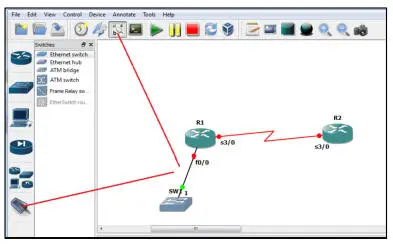
Figure 2.12. Connection to a switch. For a color version of the figure, see www.iste.co.uk/helali/systems.zip
Switches can be configured in a very generic way. To do this, we click on the switch to the right and select CONFIGURE. Now we can specify the VLAN and the mode assigned to each port.
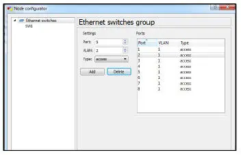
Figure 2.13. Switch configuration. For a color version of the figure, see www.iste.co.uk/helali/systems.zip
This allows us to control at least the basic aspects of a switch's configuration.
2.3.4.3. Configuring a router
Once a network infrastructure has been constructed, we move on to its configuration.
To access the router, simply double-click on it or right-click and select console. The standard console access program will open. Now we can configure the router exactly how we do with physical systems.
2.3.4.4. Adding virtual systems
It is possible to import virtual machines into GNS3, like an IOS image, or to use the cloud.
Method 1 (cloud)
Based on VirtualBox, VMware or any other virtualization software program installed on the host system executing GNS3, we can create GNS3 interfaces on our virtual machines and integrate them into GNS3.
To do this, we have to choose the host-only network interface in the virtualization software, illustrated by VMware Workstation shown in Figure 2.14, for example.
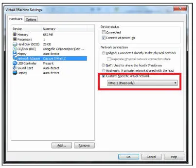
Figure 2.14. Network configuration of a virtual machine. For a color version of the figure, see www.iste.co.uk/helali/systems.zip
Next, we create a cloud connection in GNS3 via the End Devices button.
Читать дальшеИнтервал:
Закладка:
Похожие книги на «Systems and Network Infrastructure Integration»
Представляем Вашему вниманию похожие книги на «Systems and Network Infrastructure Integration» списком для выбора. Мы отобрали схожую по названию и смыслу литературу в надежде предоставить читателям больше вариантов отыскать новые, интересные, ещё непрочитанные произведения.


Обсуждение, отзывы о книге «Systems and Network Infrastructure Integration» и просто собственные мнения читателей. Оставьте ваши комментарии, напишите, что Вы думаете о произведении, его смысле или главных героях. Укажите что конкретно понравилось, а что нет, и почему Вы так считаете.