Geoff Klempner - Handbook of Large Hydro Generators
Здесь есть возможность читать онлайн «Geoff Klempner - Handbook of Large Hydro Generators» — ознакомительный отрывок электронной книги совершенно бесплатно, а после прочтения отрывка купить полную версию. В некоторых случаях можно слушать аудио, скачать через торрент в формате fb2 и присутствует краткое содержание. Жанр: unrecognised, на английском языке. Описание произведения, (предисловие) а так же отзывы посетителей доступны на портале библиотеки ЛибКат.
- Название:Handbook of Large Hydro Generators
- Автор:
- Жанр:
- Год:неизвестен
- ISBN:нет данных
- Рейтинг книги:4 / 5. Голосов: 1
-
Избранное:Добавить в избранное
- Отзывы:
-
Ваша оценка:
Handbook of Large Hydro Generators: краткое содержание, описание и аннотация
Предлагаем к чтению аннотацию, описание, краткое содержание или предисловие (зависит от того, что написал сам автор книги «Handbook of Large Hydro Generators»). Если вы не нашли необходимую информацию о книге — напишите в комментариях, мы постараемся отыскать её.
Handbook of Large Hydro Generators: Operation and Maintenance Written with a machine operator and inspector in mind,
:
Instructs readers how to perform complete machine inspections, understand what they are doing, and find solutions for any problems encountered Includes real-life, practical, field experiences so that readers can familiarize themselves with aspects of machine operation, maintenance, and solutions to common problems Benefits experienced and new power plant operators, generator design engineers and operations engineers. Is authored by industry experts who participated in the writing and maintenance of IEEE standards (IEEE C50.12 and C50.13) on the subject
is an ideal resource for scientists and engineers whose research interest is in electromagnetic and energy conversion. It is also an excellent book for senior undergraduate and graduate students majoring in energy generation, and generator operation and maintenance.
Handbook of Large Hydro Generators — читать онлайн ознакомительный отрывок
Ниже представлен текст книги, разбитый по страницам. Система сохранения места последней прочитанной страницы, позволяет с удобством читать онлайн бесплатно книгу «Handbook of Large Hydro Generators», без необходимости каждый раз заново искать на чём Вы остановились. Поставьте закладку, и сможете в любой момент перейти на страницу, на которой закончили чтение.
Интервал:
Закладка:
1.5.1 Faraday's Law of Electromagnetic Induction
This basic law of Electromagnetic Induction, derived by the genius of the great English chemist and physicist Michael Faraday (1791–1867), presents itself in two different forms:
1 A moving conductor cutting the lines of force (flux) of a constant magnetic field has a voltage induced in it.
2 A changing magnetic flux inside a loop made from a conductor material will induce a voltage in the loop.
In both instances, the rate of change of the magnetic field is the critical determinant of the resulting voltage potential. Figure 1.5-1illustrates both cases of electromagnetic induction and also provides the basic relationship between the changing flux and the voltage induced in the loop. The first case shows the relationship between the induced voltage in a wire moving across a constant field. The second case shows one of the simple rules that can be used to determine the direction of the induced voltage in the moving conductor.
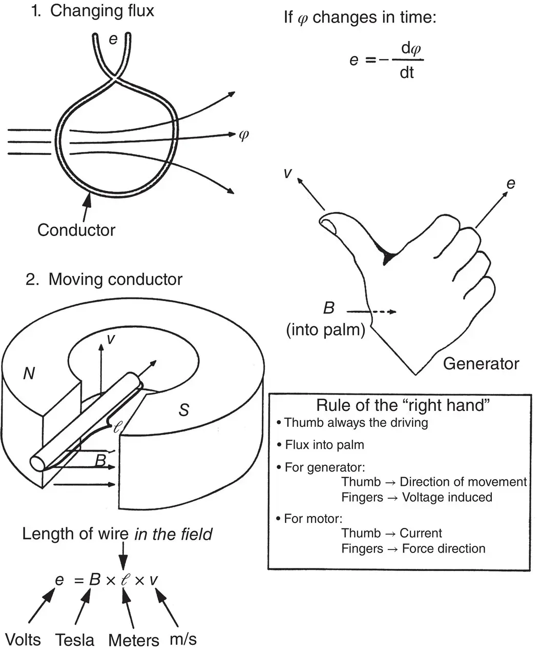
Figure 1.5-1Both forms of Faraday's basic law of electromagnetic induction. A simple rule (the “right‐hand” rule) is used to determine the direction of the induced voltage in a conductor moving across a magnetic field at a given velocity.
1.5.2 Ampere–Biot–Savart's Law
This basic law is attributed to the French physicists Andre Marie Ampere (1775–1836), Jean Baptiste Biot (1774–1862), and Victor Savart (1803–1862). In its simplest form, this law can be seen as the “reverse” of Faraday's law. Whereas Faraday's law predicts a voltage induced in a conductor moving across a magnetic field, the Ampere–Biot–Savart law establishes that a force is generated on a current‐carrying conductor located in a magnetic field.
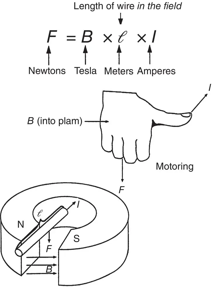
Figure 1.5-2The Ampere–Biot–Savart law of electromagnetic‐induced forces as it applies to electric rotating machines. Basic numerical relationships and a simple rule are used to determine the direction of the induced force.
Figure 1.5-2presents the basic elements of Ampere–Biot–Savart's law as applicable to electric machines. The figure also shows the existing numerical relationships, and a simple hand rule to determine the direction of the resultant force.
1.5.3 Lenz's Law of Action and Reaction
Both Faraday's law and Ampere–Biot–Savart's law neatly come together in Lenz's law, written in 1835 by the Estonian‐born physicist Heinrich Lenz (1804–1865). Lenz's law states that electromagnetic‐induced currents and forces will try to cancel the originating cause.
For example, if a conductor is forced to move, cutting lines of magnetic force, a voltage is induced in it (Faraday's law). Now, if the conductors' ends are closed together so that a current can flow, this induced current will produce (according to Ampere–Biot–Savart's law) a force acting upon the conductor. What Lenz's law states is that this force will act to oppose the movement of the conductor in its original direction.
Here, in a nutshell, is the explanation for the generating and motoring modes of operation of an electric rotating machine. This law explains why, when the load in a generator is increased (i.e. more current flows in its windings, cutting the magnetic field in the gap between rotor and stator), more force is required from the turbine to counteract the increase in induced larger forces and keep supplying the larger load.
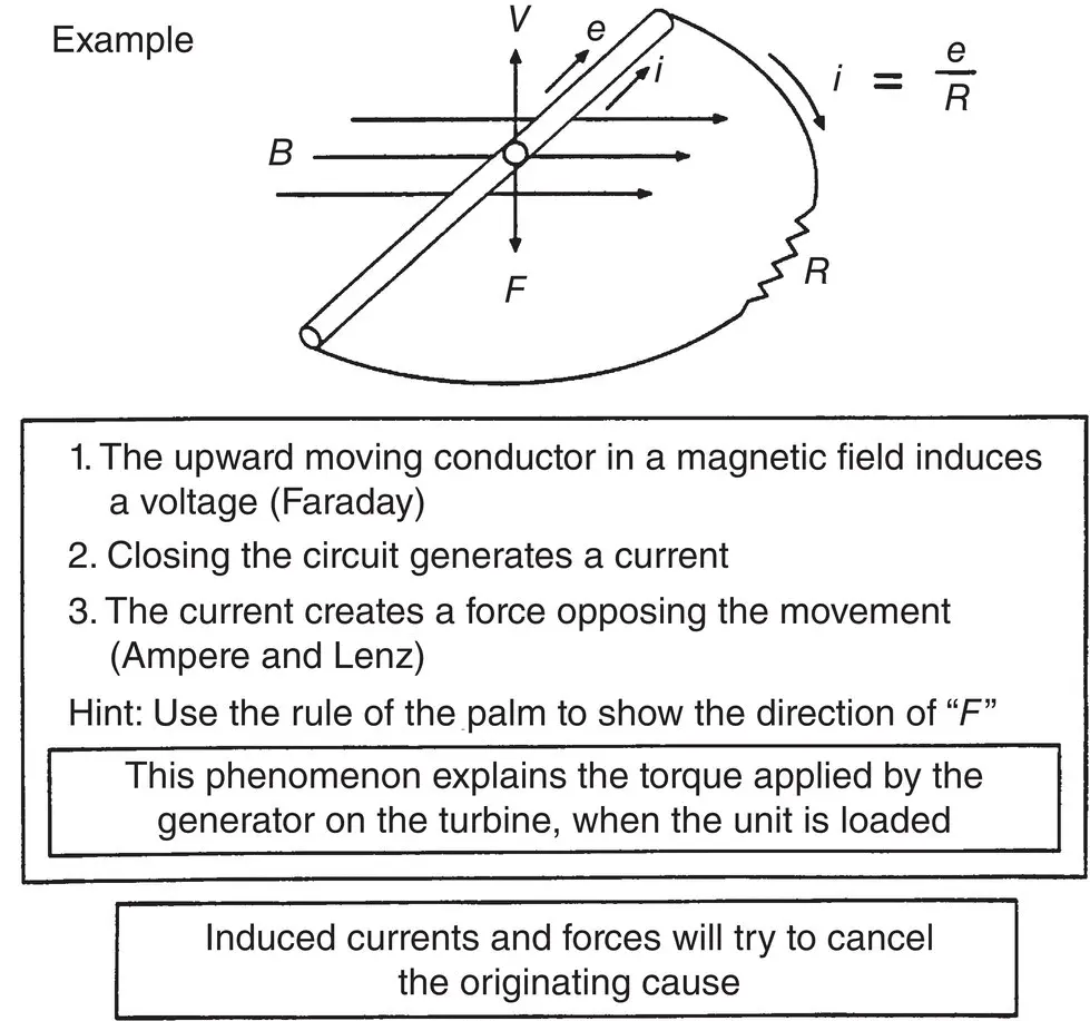
Figure 1.5-3Lenz's law as it applies to electric rotating machines. Basic numerical relationships and a simple rule are used to determine the direction of the induced forces and currents.
Similarly, Lenz's law explains the increase in the supply current of a motor as its load increases. Figure 1.5-3neatly captures the main elements of Lenz's law as it applies to electric rotating machines.
1.5.4 Electromechanical Energy Conversion
The fourth and final physical law that captures, together with the previous three, all the physical processes occurring inside an electric machine, is the “principle of energy conversion.” Within the domain of the electromechanical world of an electric rotating machine, this principle states that
All the electrical and mechanical energy flowing into the machine, less all the electrical and mechanical energy flowing out of the machine and stored in the machine, equals the energy dissipated from the machine as heat.
It is important to recognize that although mechanical and electrical energy can go into or out of the machine, the heat generated within the machine always has a negative sign, that is, heat generated in the machine is always released during the conversion process. A plus sign indicates energy going in; a minus indicates energy going out. In the case of the stored energy (electrical and mechanical), a plus sign indicates an increase of stored energy, whereas a minus sign indicates a reduction in stored energy.
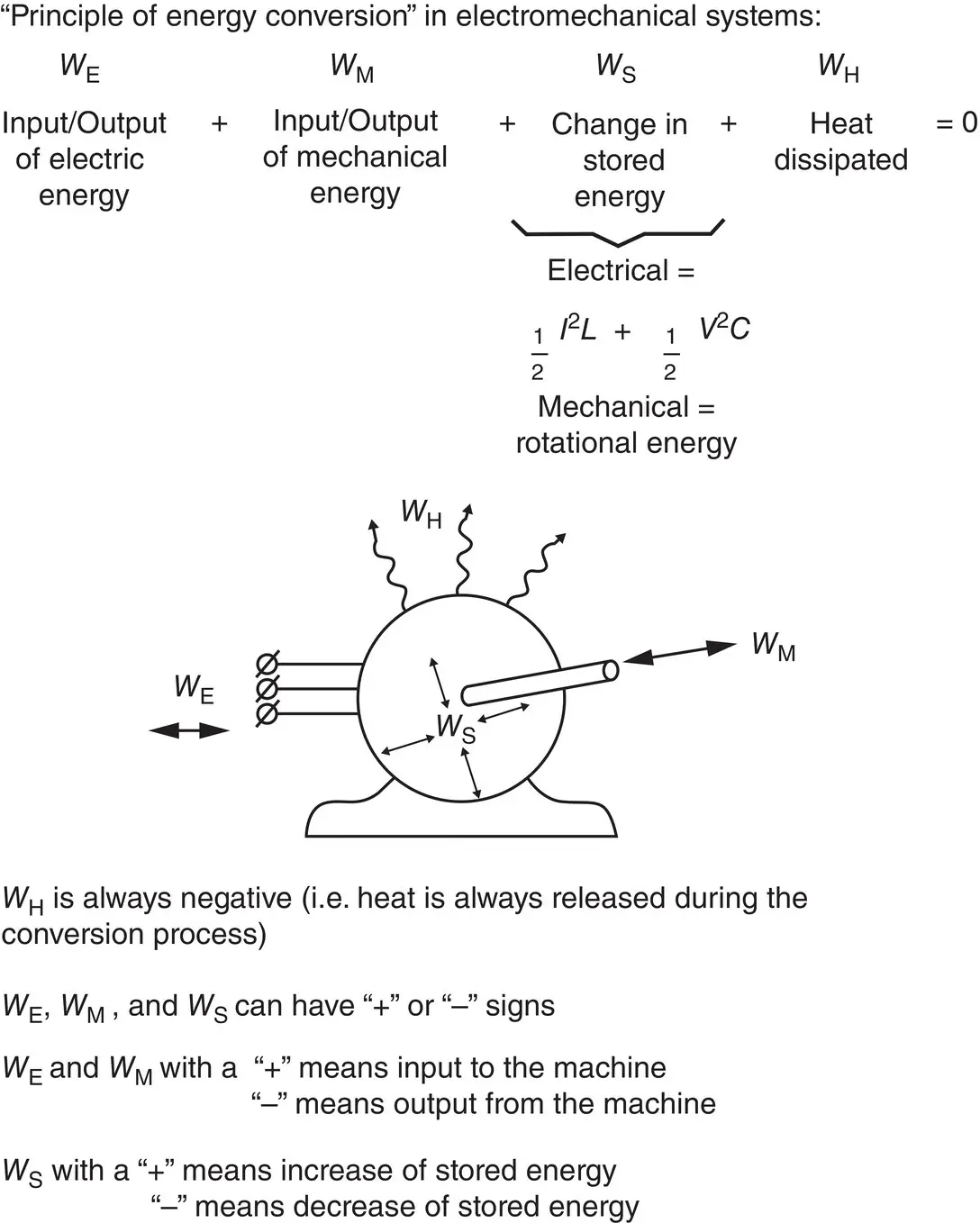
Figure 1.5-4Principle of energy conversion as applicable to electric rotating machines.
The balance between the various forms of energy in the machine will determine its efficiency and cooling requirements, as well as its critical performance and construction parameters. Figure 1.5-4depicts the principle of energy conversion as applicable to electric rotating machines.
1.6 THE SYNCHRONOUS MACHINE
The rudiments of electromagnetism have been presented along with the four basic laws of physics describing the physical processes existing in any electrical machine. Therefore, it is the right time to introduce the basic synchronous machine, which, is the type of electric machine used for all large hydro turbine driven generators.
1.6.1 Background
The birth of commercial alternating current (AC) hydro generation dates back to June 1891 with the delivery of AC power in Colorado USA from the Ames Hydro Power Station to the Gold King Mine 4.2 km away. The generator for the power plant and the motor for the mill were identical Westinghouse synchronous single-phase machines rated 73.5 kW, 3,000 volts, 133 Hz. Later in 1891 an Oerlikon synchronous 3-phase hydro generator at 180 kW, 55 volts, 40 Hz, with transformer extended power transmission 160 km from Lauffen to Frankfurt Germany during an international electrical exhibition in Frankfurt, see Figure 1.6-1. These pioneering concepts happened more than 125 years before the writing of this book and the basic principles of the hydro electrical power system are the same today.
These very early power generation experiments were instrumental in the adoption by New York’s Niagara Falls Power Company to use this technology at their Niagara Falls Adams Hydro Station. This pioneering power plant started a rapid and continuing increase of unit ratings at these falls by operating their first of ten Westinghouse 3,677 kW, 2,000 volt, 25 Hz hydro generators in August of 1895. For all practical purposes, the great DC (Edison) versus AC (Westinghouse) duel was over. It is interesting to note that although tremendous development in generator structural, magnetic and insulating materials, and manufacturing methods has occurred over the years, the basic design elements of these electric machines have remained practically unchanged. The very earliest concept was that a synchronous generator is used to drive a synchronous motor but Tesla’s induction motor quickly replaced the synchronous motor for the vast majority of electric motor applications. However the synchronous generator remained the universal machine of choice for the large-scale generation of hydroelectric power.
Читать дальшеИнтервал:
Закладка:
Похожие книги на «Handbook of Large Hydro Generators»
Представляем Вашему вниманию похожие книги на «Handbook of Large Hydro Generators» списком для выбора. Мы отобрали схожую по названию и смыслу литературу в надежде предоставить читателям больше вариантов отыскать новые, интересные, ещё непрочитанные произведения.


Обсуждение, отзывы о книге «Handbook of Large Hydro Generators» и просто собственные мнения читателей. Оставьте ваши комментарии, напишите, что Вы думаете о произведении, его смысле или главных героях. Укажите что конкретно понравилось, а что нет, и почему Вы так считаете.