Geoff Klempner - Handbook of Large Hydro Generators
Здесь есть возможность читать онлайн «Geoff Klempner - Handbook of Large Hydro Generators» — ознакомительный отрывок электронной книги совершенно бесплатно, а после прочтения отрывка купить полную версию. В некоторых случаях можно слушать аудио, скачать через торрент в формате fb2 и присутствует краткое содержание. Жанр: unrecognised, на английском языке. Описание произведения, (предисловие) а так же отзывы посетителей доступны на портале библиотеки ЛибКат.
- Название:Handbook of Large Hydro Generators
- Автор:
- Жанр:
- Год:неизвестен
- ISBN:нет данных
- Рейтинг книги:4 / 5. Голосов: 1
-
Избранное:Добавить в избранное
- Отзывы:
-
Ваша оценка:
Handbook of Large Hydro Generators: краткое содержание, описание и аннотация
Предлагаем к чтению аннотацию, описание, краткое содержание или предисловие (зависит от того, что написал сам автор книги «Handbook of Large Hydro Generators»). Если вы не нашли необходимую информацию о книге — напишите в комментариях, мы постараемся отыскать её.
Handbook of Large Hydro Generators: Operation and Maintenance Written with a machine operator and inspector in mind,
:
Instructs readers how to perform complete machine inspections, understand what they are doing, and find solutions for any problems encountered Includes real-life, practical, field experiences so that readers can familiarize themselves with aspects of machine operation, maintenance, and solutions to common problems Benefits experienced and new power plant operators, generator design engineers and operations engineers. Is authored by industry experts who participated in the writing and maintenance of IEEE standards (IEEE C50.12 and C50.13) on the subject
is an ideal resource for scientists and engineers whose research interest is in electromagnetic and energy conversion. It is also an excellent book for senior undergraduate and graduate students majoring in energy generation, and generator operation and maintenance.
Handbook of Large Hydro Generators — читать онлайн ознакомительный отрывок
Ниже представлен текст книги, разбитый по страницам. Система сохранения места последней прочитанной страницы, позволяет с удобством читать онлайн бесплатно книгу «Handbook of Large Hydro Generators», без необходимости каждый раз заново искать на чём Вы остановились. Поставьте закладку, и сможете в любой момент перейти на страницу, на которой закончили чтение.
Интервал:
Закладка:
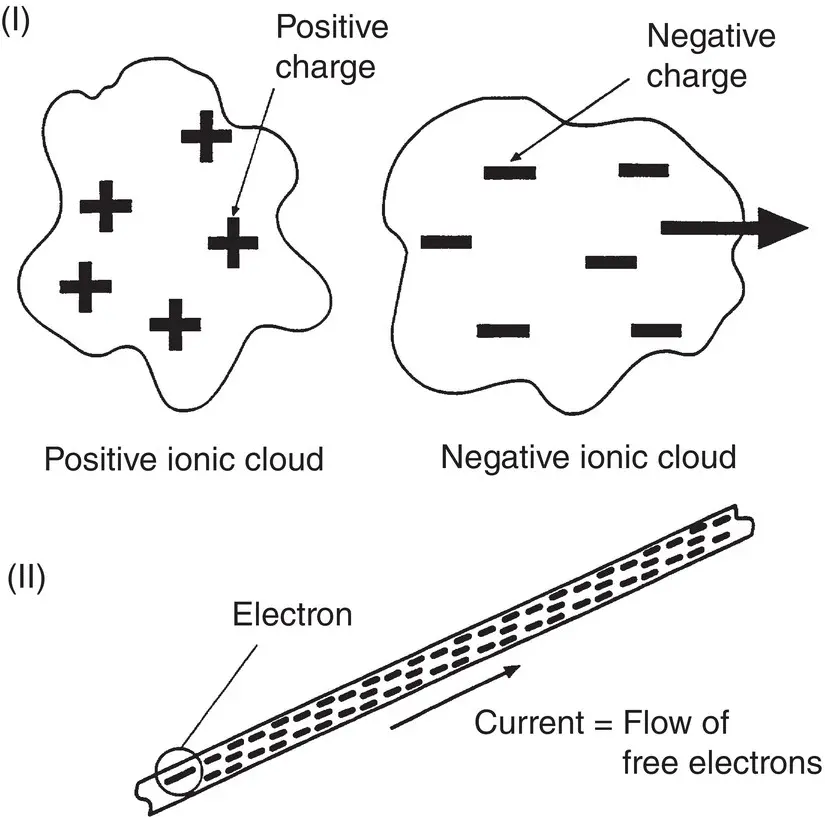
Figure 1.1-8Electricity. (I) Ionic clouds of positive and negative currents. The positive clouds are normally atoms that lost one or more electrons; the negative clouds are normally free electrons. This effect can be found inside the generator as partial discharge in the stator winding. (II) The flow of electrons inside a conductor material, for example, the copper windings of the rotor and stator.
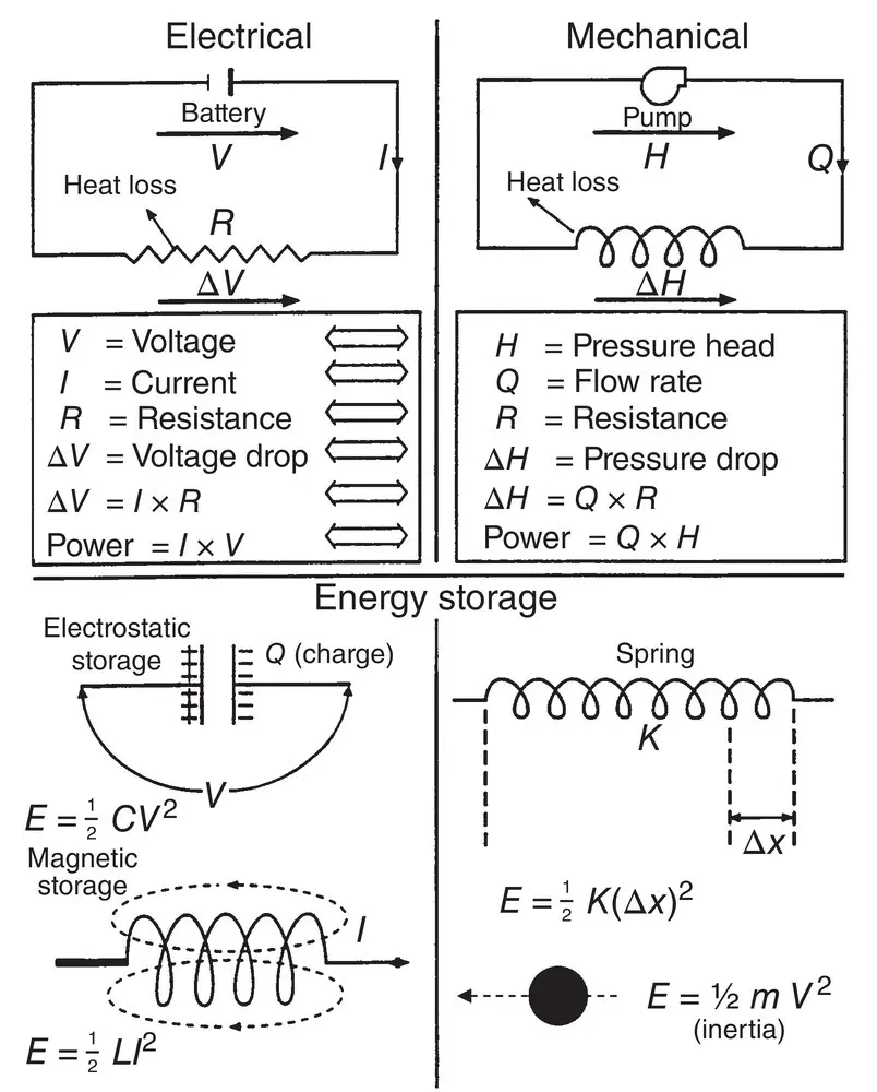
Figure 1.2-1Electrical–mechanical equivalence.
1.2 ELECTRICAL–MECHANICAL EQUIVALENCE
There is an interesting equivalence between the various parameters describing electrical and mechanical forms of energy. People with either electrical or mechanical backgrounds find this equivalence useful to the understanding of the physical process in either form of energy. Figure 1.2-1describes the various forms of electrical–mechanical equivalence.
1.3 ALTERNATING CURRENT (AC)
Synchronous generators operate with both alternating‐current (AC) and direct‐current (DC) electric power. The DC can be considered a particular case of the general AC, with frequency equal to zero.
The frequency of an alternating circuit is a measure of the number of times the currents and/or voltages change direction (polarity) in a unit of time. The hertz (Hz) is the universally accepted unit of frequency, and measures cycles per second. One Hz equals one cycle per second. Alternating currents and voltages encountered in the world of industrial electric power are for all practical purposes of constant frequency. This is important because periodic systems, namely systems that have constant frequency and sinusoidal signals, allow the currents and voltages to be represented by phasors.
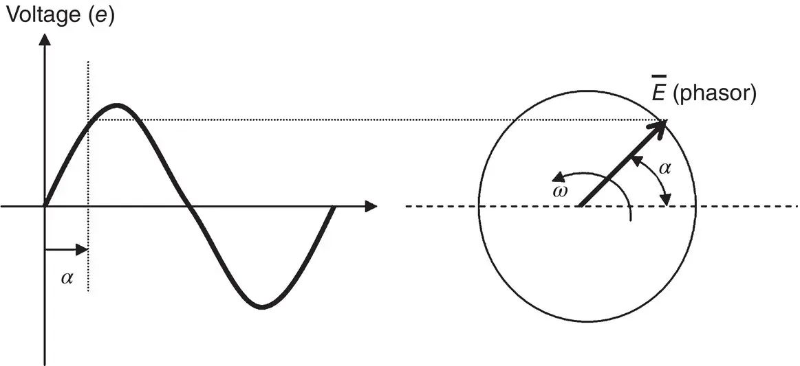
Figure 1.3-1A phasor E that can represent the voltage impressed on a circuit.
A phasor is a rotating vector. The benefit of using phasors in electrical engineering analysis is that it greatly simplifies the calculations required to solve circuit problems.
Figure 1.3-1depicts a phasor of magnitude E , and its corresponding sinusoidal trace representing the instantaneous value of the voltage quantity e . The magnitude E represents the maximum value of voltage ( e ).
The phasor is made of a vector with magnitude proportional to the magnitude of E , rotating at a constant rotational speed ω . The convention is that phasors rotate counterclockwise. The vertical projection of the phasor results in a sinusoid representing the instantaneous voltage ( e ) existing at any time. In Figure 1.3-1, α = ω × t , where t is the time elapsed from its zero crossing.
When a sinusoidal voltage is applied to a closed circuit, a current will flow in it. After a while, the current will have a sinusoidal shape (this is called the steady‐state current component) and the same frequency as the voltage. An interesting phenomenon in periodic circuits is that the resulting angle between the applied voltage and the current depends on certain characteristics of the circuit. These characteristics combine into one representative parameter, impedance and are broken down into resistive, capacitive, and inductive . The angle between the voltage and the current in the circuit is called the power factor angle and is defined as φ . The cosine of the same angle is called the power factor of the circuit or, for short, the PF.
In the case of a circuit having only resistances, the voltages and currents are in phase , meaning that the angle between them equals zero. Figure 1.3-2shows the various parameters encountered in a resistive circuit. This is a representation of a sinusoidal voltage of magnitude “ E ” applied on a circuit with a resistive load “ R .” The schematics show the resultant current ( i ) in phase with the voltage ( v ). It also shows the phasor representation of the voltage and current. It is important to note that resistances have the property of generating heat when a current flows through them. The heat generated equals the square of the current times the value of the resistance. When the current is measured in amperes and the resistance in ohms, the resulting power dissipated as heat is given in watts. In electrical machines, this heat represents a loss of energy. One of the fundamental requirements in designing an electric machine is the efficient removal of the energy resulting from these resistive losses, with the purpose of limiting the temperature rise of the internal components of the machine. In resistive circuits, the instantaneous power delivered by the source to the load equals the product of the instantaneous values of the voltage and the current. When the same sinusoidal voltage is applied across the terminals of a circuit with capacitive or inductive characteristics, the steady‐state current will exhibit an angular (or time) displacement in relation to the driving voltage.
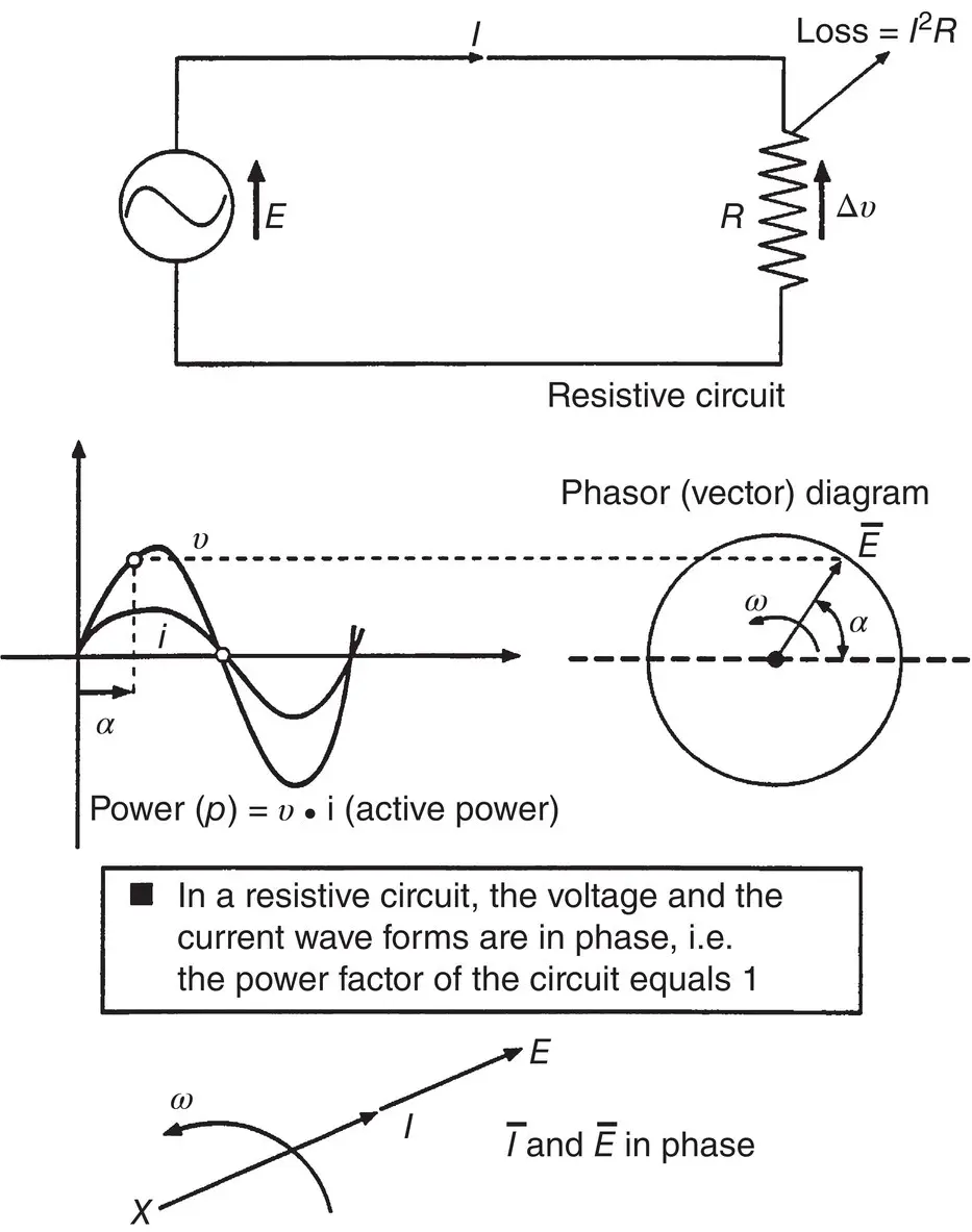
Figure 1.3-2Alternating circuits (resistive).
The magnitude of the angle (or power factor) depends on how capacitive or inductive the load is. In a purely capacitive circuit, the current will lead the voltage by 90°, whereas in a purely inductive one, the current will lag the voltage by 90° (see Figure 1.3-3). Here, the sinusoidal voltage E is applied to a circuit comprised of resistive, capacitive, and inductive elements. The resulting angle between the current and the voltage depends on the value of the resistance, capacitance, and inductance of the load.
A circuit that has capacitive or inductive characteristics is referred to as being a reactive circuit. In such a circuit, the following parameters are defined:
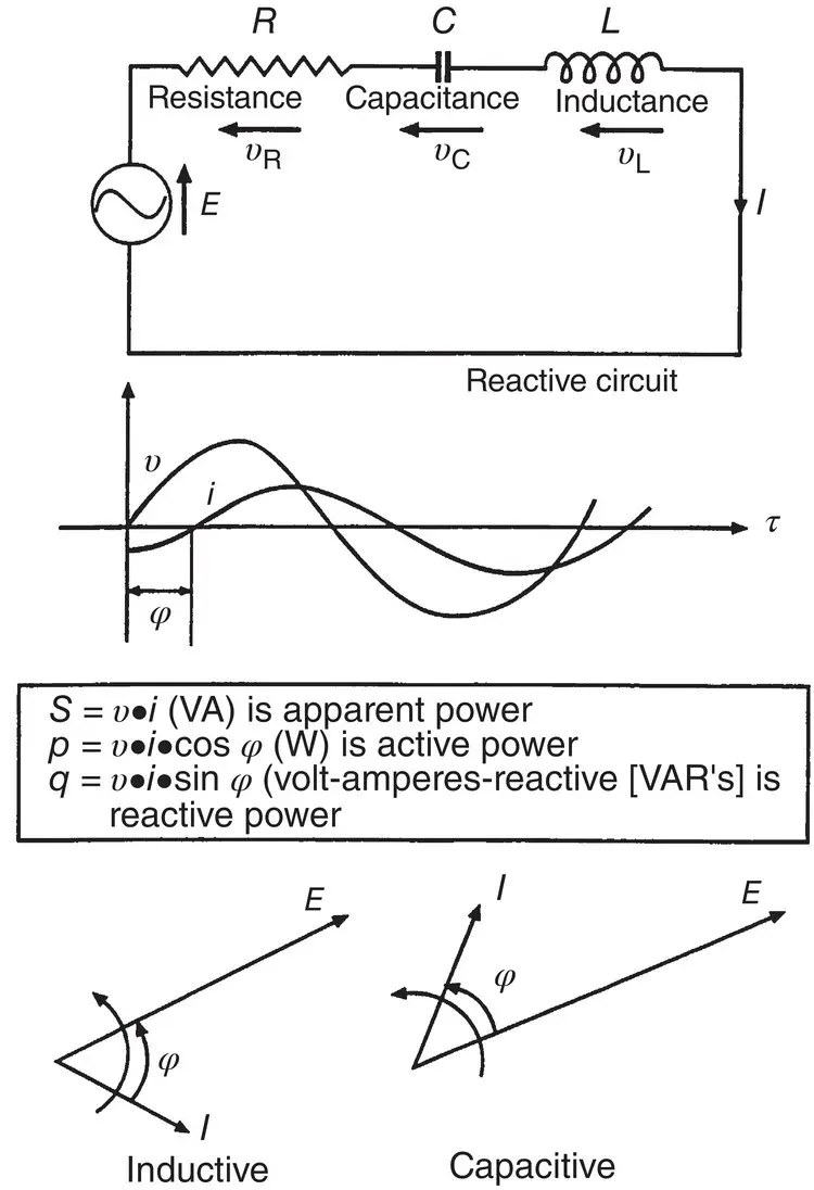
Figure 1.3-3Alternating circuits (resistive‐inductive‐capacitive).
| S: The apparent power | S = E × I , given in units of volt‐amperes or VA. |
| P: The active power | P = E × I × cos φ , where φ is the angle between the voltage and the current. P is given in units of watts. |
| Q: The reactive power | Q = E × I × sin φ , given in units of volt‐amperes‐reactive or VAR. |
The active power P of a circuit indicates a real energy flow. This is power that may be dissipated on a resistance as heat, or may be transformed into mechanical energy. However, the use of the word “power” in the definition of S and Q has been an unfortunate choice that has resulted in confounding most individuals without an electrical engineering background for many years. The fact is that apparent power and reactive power do not represent any measure of real energy. They do represent the reactive characteristic of a given load or circuit, and the resulting angle (power factor) between the current and voltage. This angle between voltage and current significantly affects the operation of an electric machine.
Читать дальшеИнтервал:
Закладка:
Похожие книги на «Handbook of Large Hydro Generators»
Представляем Вашему вниманию похожие книги на «Handbook of Large Hydro Generators» списком для выбора. Мы отобрали схожую по названию и смыслу литературу в надежде предоставить читателям больше вариантов отыскать новые, интересные, ещё непрочитанные произведения.


Обсуждение, отзывы о книге «Handbook of Large Hydro Generators» и просто собственные мнения читателей. Оставьте ваши комментарии, напишите, что Вы думаете о произведении, его смысле или главных героях. Укажите что конкретно понравилось, а что нет, и почему Вы так считаете.