J. C. Das - Arc Flash Hazard Analysis and Mitigation
Здесь есть возможность читать онлайн «J. C. Das - Arc Flash Hazard Analysis and Mitigation» — ознакомительный отрывок электронной книги совершенно бесплатно, а после прочтения отрывка купить полную версию. В некоторых случаях можно слушать аудио, скачать через торрент в формате fb2 и присутствует краткое содержание. Жанр: unrecognised, на английском языке. Описание произведения, (предисловие) а так же отзывы посетителей доступны на портале библиотеки ЛибКат.
- Название:Arc Flash Hazard Analysis and Mitigation
- Автор:
- Жанр:
- Год:неизвестен
- ISBN:нет данных
- Рейтинг книги:5 / 5. Голосов: 1
-
Избранное:Добавить в избранное
- Отзывы:
-
Ваша оценка:
Arc Flash Hazard Analysis and Mitigation: краткое содержание, описание и аннотация
Предлагаем к чтению аннотацию, описание, краткое содержание или предисловие (зависит от того, что написал сам автор книги «Arc Flash Hazard Analysis and Mitigation»). Если вы не нашли необходимую информацию о книге — напишите в комментариях, мы постараемся отыскать её.
is the most comprehensive reference guide available on all aspects of arc flash hazard calculations, protective current technologies, and worker safety in electrical environments. Detailed chapters cover protective relaying, unit protection systems, arc-resistant equipment, arc flash analyses in DC systems, and many more critical topics.
Now in its second edition, this industry-standard resource contains fully revised material throughout, including a new chapter on calculation procedures conforming to the latest
. Updated methodology and equations are complemented by new practical examples and case studies. Expanded topics include risk assessment, electrode configuration, the impact of system grounding, electrical safety in workplaces, and short-circuit currents. Written by a leading authority with more than three decades' experience conducting power system analyses, this invaluable guide:
Provides the latest methodologies for flash arc hazard analysis as well practical mitigation techniques, fully aligned with the updated
Explores an inclusive range of current technologies and strategies for arc flash mitigation Covers calculations of short-circuits, protective relaying, and varied electrical system configurations in industrial power systems Addresses differential relays, arc flash sensing relays, protective relaying coordination, current transformer operation and saturation, and more Includes review questions and references at the end of each chapter Part of the market-leading
the second edition of Arc Flash Hazard Analysis and Mitigation remains essential reading for all electrical engineers and consulting engineers.
Arc Flash Hazard Analysis and Mitigation — читать онлайн ознакомительный отрывок
Ниже представлен текст книги, разбитый по страницам. Система сохранения места последней прочитанной страницы, позволяет с удобством читать онлайн бесплатно книгу «Arc Flash Hazard Analysis and Mitigation», без необходимости каждый раз заново искать на чём Вы остановились. Поставьте закладку, и сможете в любой момент перейти на страницу, на которой закончили чтение.
Интервал:
Закладка:
Example 1.5
Repeat Example 1.4with rigorous calculations.
Table 1.8equations do not specify the gap length and also the system grounding. As the equations are for the maximum incident energy, it can be assumed that the system is ungrounded. Also for Table 1.8equations, a working distance of 610 mm (2 ft) is specified in 1584 Guide. Thus, there are qualifications and compromises in using these equations.
To start the rigorous calculations, a time–current plot of settings on 800-A LVPCB and 400-A MCCB is shown in Figure 1.10. The maximum time on the trip band is used, shown by dots in this figure. This figure is based on circuit breakers of a certain manufacturer. This shows that the LVPCB maximum ST delay band is used, as the approximate equations are based upon this assumption. The opening time of the low voltage circuit breakers is built in the time–current plots supplied by the manufacturer . Thus, we consider the maximum operating times as shown by bold dots in Figure 1.10. These arcing times are 0.5 second for 800-A LVPCB and 0.017 second for the 400-A MCCB.
The results of the calculations are in Table 1.13. The calculations have been made for grounded and ungrounded systems, and with gaps and working distances as shown. A LVPCB will be provided in a lineup of LV switchgear, and a working distance of 610 mm and gap of 32 mm are applicable as per IEEE 1584 Guide. A 400-A MCCB may be installed in a MCC, where the working distance is reduced to 455 mm and the gap is 25 mm. The variations in the results are apparent and significant for an application.
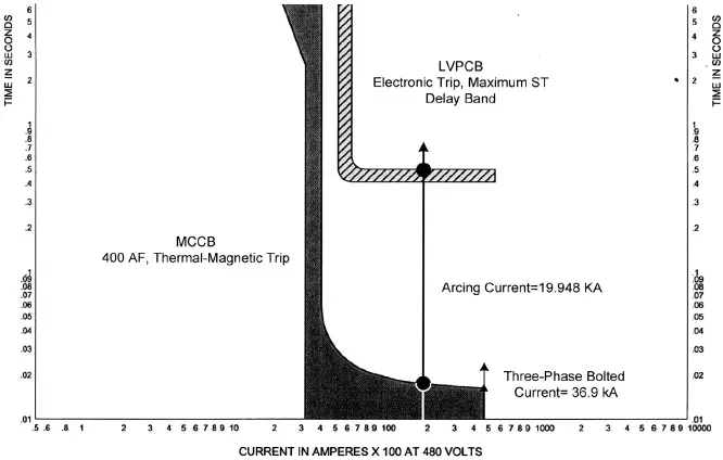
Figure 1.10. To illustrate the arcing time for low voltage circuit breakers, at the calculated arcing current.
TABLE 1.13.Arc Flash Calculations, Example 1.5
| Breaker | Bolted Fault (kA) | Arcing Fault (kA) | Trip Time (sec) | Opening Time (sec) | Arc Time (sec) | Ground | Gap (mm) | Working Distance (in) | Arc Flash Boundary (in) | Incident Energy Cal/cm 2 | PPE |
| 800-A | 36.8 | 19.95 | 0.5 | 0 | No | 32 | 610 | 198 | 27 | 4 | |
| 800-A LVPCB | 36.8 | 19.95 | 0.5 | 0 | No Yes | 32 32 | 610 610 | 198 166 | 27 21 | 4 3 | |
| 400-A | 36.8 | 19.95 | 0.017 | 0 | No | 25 | 455 | 21 | 1.5 | 1 | |
| MCCB | Yes | 25 | 455 | 18 | 1.2 | 0 | |||||
| (MCC) |
1.15 REDUCING ARC FLASH HAZARD
Electrical arc flash hazard cannot be reduced to HRC zero even in small distribution systems. Electrical power systems vary in complexity—an industrial power system may have a number of in-plant generators in cogeneration mode with utility tie and consume 200 MW of power with hundreds of unit substations and extensive power distribution at medium voltages and low voltage levels, containing motors of thousands of horsepower, a single motor exceeding ratings of 25,000 hp or more and multiple utility interconnections. Conversely, a system with a one or two 480 V transformers of 1000 KVA will also be classified as industrial systems. Thus, it is difficult to lay down all the general rules for reducing arc flash hazard in power systems.
This book contains many study cases and examples, and it is recommended that a reader may do a first reading of the book to grasp an overall picture, followed by a subsequent study. The following common parameters can be stated for arc flash hazard reduction:
1 Reduce the short-circuit currents by proper system designs and load distribution. The arcing current is a function of the bolted three-phase current, and its reduction in the first place will reduce the arc flash hazard (see Chapters 5and 6).
2 Manipulate the protection and protective device coordination without sacrificing selectivity. Generally, it can be said that reducing the short-circuit currents in an existing system will be practically impossible, but the protective relaying can be manipulated to reduce the arcing time. See Chapters 7through 14, which discuss differential protections, arc flash detection protection, zone selective interlocking, use of maintenance mode switches to alter the protective relay settings, application of modern multifunction microprocessor-based protective relays, and coordination on instantaneous basis with current limiting devices.
3 Consider high resistance grounding systems—though the IEEE equations give a lower incident energy for solidly grounded systems, as compared with resistance grounded or high resistance grounded systems; because it takes a safe stance that single line-to-ground faults will quickly escalate to three-phase faults; yet approximately 70% of the faults start as single line-to-ground faults. The single line-to-ground faults in solidly grounded systems can be even higher than the three-phase faults. See Chapter 4.
The IEEE Guide equations reveal that the incident energy and the resulting arc flash hazard for a certain equipment type depends only upon these three parameters as stated above. Yet there are many aspects to be considered for a workers safety, discussed above and in the chapters to follow:
Remote operation, avoiding human machine interface to avoid human errors during routine operation
Remote racking of circuit breakers
Proper system designs and maintenance. See 10 bulleted items describing design features and maintenance in Chapter 2.
Proper worker training and documentation of safety procedures, and safety awareness
Proper testing, online monitoring, and diagnostics of the systems
Proper record keeping
Applications of new equipments and technologies for arc flash reduction
Proper rigorous arc flash hazard studies, labeling, and use of appropriate PPE
Adherence to safety codes, standards, and recommended practices
Remote operation, avoiding human machine interface to avoid human errors during routine operation
Remote racking of circuit breakers
1.15.1 Reduction
The protection system, coordination and suitable selection of additional protective devices can reduce the arcing times. Examples are differential protection, light sensing supervised by current signature, zone interlocking, arc flash maintenance switches which bring alternative relay settings into operation.
In some cases the arc fault current can be low resulting in increased fault clearing time. For example, the fault on the secondary side of a transformer, which is used by the transformer primary protection device. Due to ratio of transformation this current will be reduced resulting in prolonged clearing time. A secondary protective relay can be applied which will transfer trip primary proactive device.
Well-planned procedures, work practices and training can avoid arc flash hazards. Remote racking, remote control panels for switching, supervisory controls can help worker for safe operation from a distance outside the arc flash boundary. Infra-red windows, partial discharge sensors can be very helpful diagnostic tools.
Arc-resistant equipment can be used.
TABLE 1.14. Measures to Protect Against Arc Flash
| Mitigation | Type | Advantages | Disadvantages | Recommendations |
| Compartmentalization (IEC type-4b or ANSI equivalent barriers and boots | Prevention | Reduces the likelihood of arc flash by compartmentalization and insulating energized parts | Equivalent to a guard on a saw. Hazard is still present. Maintenance and testing may require exposure to energized parts | It does not reduce the energy available, it does reduce the probability of a fault. Compartmentalization or change incident energy calculation. |
| Arc-resistant equipment | Containment (passive) | Protects the worker by directing energy away from the worker when required covers are on. Tested per IEEE Std. C37.20.7 | Maintenance and testing may require removal of covers. Equipment is exposed to damage and has a larger footprint. May require second migration means to stay within rated arcing duration especially at LV | This measure offers protection for specific tasks, but does not reduce available energy. This measure is recommended where active mitigation methods are not acceptable. |
| High-speed shorting switch | Active (reduction) | Fights fire with fire. Re-directs arc flash energy into the bus by creating an intentional bolted fault; may use optical, differential and current waveform recognition. | Unconventional method and requires additional equipment. | May qualify as arc resistant per IEEE Std. 37.20.7. Needs robust controls to minimize chances of nuisance operation. |
| ZSI (blocking schemes) | Active (reduction) | Communication-aided transfer trip scheme that reduces breaker trip time and amount of energy released | Requires communication wiring between breakers. Trip units or relays must be installed with ZSI capability | Recommended for LV applications. Also available with some MV relays. |
TABLE 1.15. Matrix of Sample Arc Flash Mitigation Measures
Читать дальшеИнтервал:
Закладка:
Похожие книги на «Arc Flash Hazard Analysis and Mitigation»
Представляем Вашему вниманию похожие книги на «Arc Flash Hazard Analysis and Mitigation» списком для выбора. Мы отобрали схожую по названию и смыслу литературу в надежде предоставить читателям больше вариантов отыскать новые, интересные, ещё непрочитанные произведения.


Обсуждение, отзывы о книге «Arc Flash Hazard Analysis and Mitigation» и просто собственные мнения читателей. Оставьте ваши комментарии, напишите, что Вы думаете о произведении, его смысле или главных героях. Укажите что конкретно понравилось, а что нет, и почему Вы так считаете.