J. C. Das - Arc Flash Hazard Analysis and Mitigation
Здесь есть возможность читать онлайн «J. C. Das - Arc Flash Hazard Analysis and Mitigation» — ознакомительный отрывок электронной книги совершенно бесплатно, а после прочтения отрывка купить полную версию. В некоторых случаях можно слушать аудио, скачать через торрент в формате fb2 и присутствует краткое содержание. Жанр: unrecognised, на английском языке. Описание произведения, (предисловие) а так же отзывы посетителей доступны на портале библиотеки ЛибКат.
- Название:Arc Flash Hazard Analysis and Mitigation
- Автор:
- Жанр:
- Год:неизвестен
- ISBN:нет данных
- Рейтинг книги:5 / 5. Голосов: 1
-
Избранное:Добавить в избранное
- Отзывы:
-
Ваша оценка:
Arc Flash Hazard Analysis and Mitigation: краткое содержание, описание и аннотация
Предлагаем к чтению аннотацию, описание, краткое содержание или предисловие (зависит от того, что написал сам автор книги «Arc Flash Hazard Analysis and Mitigation»). Если вы не нашли необходимую информацию о книге — напишите в комментариях, мы постараемся отыскать её.
is the most comprehensive reference guide available on all aspects of arc flash hazard calculations, protective current technologies, and worker safety in electrical environments. Detailed chapters cover protective relaying, unit protection systems, arc-resistant equipment, arc flash analyses in DC systems, and many more critical topics.
Now in its second edition, this industry-standard resource contains fully revised material throughout, including a new chapter on calculation procedures conforming to the latest
. Updated methodology and equations are complemented by new practical examples and case studies. Expanded topics include risk assessment, electrode configuration, the impact of system grounding, electrical safety in workplaces, and short-circuit currents. Written by a leading authority with more than three decades' experience conducting power system analyses, this invaluable guide:
Provides the latest methodologies for flash arc hazard analysis as well practical mitigation techniques, fully aligned with the updated
Explores an inclusive range of current technologies and strategies for arc flash mitigation Covers calculations of short-circuits, protective relaying, and varied electrical system configurations in industrial power systems Addresses differential relays, arc flash sensing relays, protective relaying coordination, current transformer operation and saturation, and more Includes review questions and references at the end of each chapter Part of the market-leading
the second edition of Arc Flash Hazard Analysis and Mitigation remains essential reading for all electrical engineers and consulting engineers.
Arc Flash Hazard Analysis and Mitigation — читать онлайн ознакомительный отрывок
Ниже представлен текст книги, разбитый по страницам. Система сохранения места последней прочитанной страницы, позволяет с удобством читать онлайн бесплатно книгу «Arc Flash Hazard Analysis and Mitigation», без необходимости каждый раз заново искать на чём Вы остановились. Поставьте закладку, и сможете в любой момент перейти на страницу, на которой закончили чтение.
Интервал:
Закладка:
In NFPA 70E 2012, the hazard risk category (HRC) 2* is eliminated. All HRC 2 tasks will require the use of a balaclava under an arc-rated face shield or the use of an arc-rated hood. Commercially, arc-rated outfits even up to 100 cal/cm 2are available, still for category 4 applications.
1.10 HAZARD BOUNDARIES
The boundaries are defined in NFPA, and the following synopsis is relevant here ( Figure 1.9).
The flash protection boundary is the distance at which the threshold of second-degree burns can occur and the incident energy release is 1.2 cal/cm 2(5.0 J/cm 2). This is the boundary that is calculated by computer-based programs and IEEE Guide equations. Inside the boundary, the energy level will be higher. This boundary should not be crossed by any one, including a qualified person, without wearing the required PPE, ( Table 1.8). The PPE outfits are designed to minimize the risk of sustaining energy greater than 1.2/cal cm 2. That is, the threshold of second-degree burns can still occur even with appropriate PPE, and these burns are considered curable .
Unqualified persons, that is, those not specifically trained to carry out the required tasks, are safe when they stay away from the energized part of a certain distance, which is the limited approach boundary. They should not cross the limited approach boundary and arc flash boundary unless escorted by a qualified person.
Crossing the restricted approach boundary means that special shock prevention techniques and equipment are required, and an unqualified person is not allowed to cross this boundary. Finally, the prohibited approach boundary establishes the space that can be crossed only, as if a live contact with exposed energized conductors or circuits was planned.
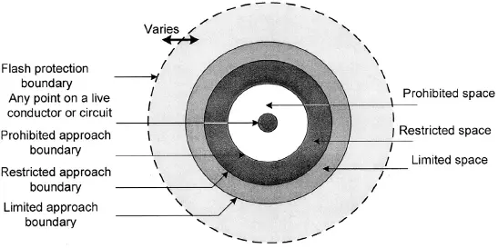
Figure 1.9. Hazard boundaries around an arcing source, adapted from NFPA 70E. Source : Reference [17].
TABLE 1.9.Limited Approach and Restricted Approach Boundaries
Source : NFPA 70E [17]. © 2012 National Fire Protection Association. (All details in the NFPA table have not been reproduced.)
| System Voltage Range | Limited Approach Boundary | ||
| Phase-to-Phase | Exposed Movable Conductor (i.e., Overhead Line Conductors Supported on Poles) | Exposed Fixed Circuit Part | Restricted Approach Boundary, Included Inadvertent Movement Adder |
| Less than 50 V | Not specified | Not specified | Not specified |
| 50–300 V | 3.0 m | 1.0 m | Avoid contact |
| 301–750 V | 3.0 m | 1.0 m | 0.3 m |
| 751 V–15 kV | 3.0 m | 1.5 m | 0.7 m |
| 15.1–36 kV | 3.0 m | 1.8 m | 0.8 m |
| 36.1–46 kV | 3.0 m | 2.5 m | 0.8 m |
| 46.1–72.5 kV | 3.0 m | 2.5 m | 1.0 m |
| 72.6–121 kV | 3.3 m | 2.5 m | 1.02 m |
| 138–145 kV | 3.4 m | 3.0 m | 1.15 m |
The limited approach, restricted approach, and prohibited approach boundaries are all defined based upon the system voltage. No calculations are required for establishing these boundaries. Table 1.9illustrates the limited approach and restricted approach boundaries based upon NFPA 70E.
1.10.1 Working Distance
Working distance is defined as the closest distance to a worker’s body excluding hands and arms. IEEE 1584 Guide [9] specifies required working distances ( Table 1.6). For the 15-kV switchgear, it is 36 in, while for a 480-V MCC, it is 18 in. A larger working distance reduces the incident energy and therefore the HRC. Recommendations of IEEE for the working distances are followed in the calculations in this book. The working distance does exclude hands and arms, which will be much closer to the seat of arc. It is the vital organs like eyes, chest, and heart that are at the working distance from the seat of the arc. This assumes that a worker does not stick his head inside the switchgear door!
1.10.2 Arc Flash Labels
The labeling on the equipment contains the following data:
system voltage
arc flash boundary
PPE category
incident energy release in cal/cm2
working distance
restricted approach boundary
prohibited approach boundary
TABLE 1.10.Arc Flash Boundary and Incident Energy Release for 30 kA of Bolted Fault Current (Arc Flash Current = 28.58 kA rms) in 13.8-kV Switchgear, 13.8-kV System Resistance Grounded, Working Distance = 36″, Gap = 153 mm
Source : Reference [17]. © 2012 National Fire Protection Association.
| Arc Duration in Seconds | Arc Flash Boundary in Inches | Energy, cal/cm 2 |
| 0.058 | 74 | |
| 0.5 | 851 | 26 |
| 1.0 | 1736 | 52 |
| 1.5 | 2633 | 78 |
| 2 | 3539 | 104 |
equipment identification
the protective device identification that clears the fault.
The labels can be generated on a variety of media, including plastic weatherproof laminates, and most commercial arc flash analysis program will allow custom designing the labels. A user can choose what goes on the label, including the description of PPE. Even the type fonts can be user selectable.
In NFPA 70E 2012, equipment labeling has been reworded to reflect Article 110.16 of the NEC. Each label must contain the incident energy at working distance or the arc rating of the required PPE, or the maximum HRC for that type of equipment. Also, arc flash boundary needs to be specified.
1.11 MAXIMUM DURATION OF AN ARC FLASH EVENT AND ARC FLASH BOUNDARY
A maximum duration of 2 seconds for the total fault clearance time of an arc flash event is considered, though, in some cases, the fault clearance time can be higher. In IEEE 1584 Guide Annexure B, it is stated that: “if the time is longer than 2 seconds, consider how long a person is likely to remain in the location of the arc-flash. It is likely that a person exposed to arc flash will move away quickly, if it is physically possible and 2 seconds is a reasonable maximum time for calculations. A person in a bucket truck or a person who has crawled into equipment may need more time to move away.”
Tables 1.10and 1.11show the arc flash boundary calculations according to IEEE 1584 Guide equations for a bolted three-phase fault current of 30 kA, in 13.8-kV switchgear, 13.8-kV system resistance grounded, and also in a 480-V MCC, and 480-V system high resistance grounded.
For a 30-kA, 2-second fault in 13.8-kV switchgear, the incident energy boundary is 3539 in equal to 295 ft. For 1-second fault duration, it is 144.6 ft. The arc flash boundary at which a worker can be exposed to 1.2 cal/cm 2of incident energy and sustain threshold of second degree burns seems to be very large.
The working space, in an electrical room switchgear installation in front of electrical equipment, is limited and may be as low as 5–6 ft, and must meet NEC requirements. Many companies, as a policy, keep the electrical rooms locked, and a worker must have the required PPE outfit before entering the electrical rooms.
TABLE 1.11.Arc Flash Boundary and Incident Energy Release for 30 kA of Bolted Fault Current (Arc Flash Current = 16.76 kA rms) in 480-V MCC, 480-V System High Resistance Grounded, Working Distance = 18″, Gap = 25 mm
Читать дальшеИнтервал:
Закладка:
Похожие книги на «Arc Flash Hazard Analysis and Mitigation»
Представляем Вашему вниманию похожие книги на «Arc Flash Hazard Analysis and Mitigation» списком для выбора. Мы отобрали схожую по названию и смыслу литературу в надежде предоставить читателям больше вариантов отыскать новые, интересные, ещё непрочитанные произведения.


Обсуждение, отзывы о книге «Arc Flash Hazard Analysis and Mitigation» и просто собственные мнения читателей. Оставьте ваши комментарии, напишите, что Вы думаете о произведении, его смысле или главных героях. Укажите что конкретно понравилось, а что нет, и почему Вы так считаете.