J. C. Das - Arc Flash Hazard Analysis and Mitigation
Здесь есть возможность читать онлайн «J. C. Das - Arc Flash Hazard Analysis and Mitigation» — ознакомительный отрывок электронной книги совершенно бесплатно, а после прочтения отрывка купить полную версию. В некоторых случаях можно слушать аудио, скачать через торрент в формате fb2 и присутствует краткое содержание. Жанр: unrecognised, на английском языке. Описание произведения, (предисловие) а так же отзывы посетителей доступны на портале библиотеки ЛибКат.
- Название:Arc Flash Hazard Analysis and Mitigation
- Автор:
- Жанр:
- Год:неизвестен
- ISBN:нет данных
- Рейтинг книги:5 / 5. Голосов: 1
-
Избранное:Добавить в избранное
- Отзывы:
-
Ваша оценка:
Arc Flash Hazard Analysis and Mitigation: краткое содержание, описание и аннотация
Предлагаем к чтению аннотацию, описание, краткое содержание или предисловие (зависит от того, что написал сам автор книги «Arc Flash Hazard Analysis and Mitigation»). Если вы не нашли необходимую информацию о книге — напишите в комментариях, мы постараемся отыскать её.
is the most comprehensive reference guide available on all aspects of arc flash hazard calculations, protective current technologies, and worker safety in electrical environments. Detailed chapters cover protective relaying, unit protection systems, arc-resistant equipment, arc flash analyses in DC systems, and many more critical topics.
Now in its second edition, this industry-standard resource contains fully revised material throughout, including a new chapter on calculation procedures conforming to the latest
. Updated methodology and equations are complemented by new practical examples and case studies. Expanded topics include risk assessment, electrode configuration, the impact of system grounding, electrical safety in workplaces, and short-circuit currents. Written by a leading authority with more than three decades' experience conducting power system analyses, this invaluable guide:
Provides the latest methodologies for flash arc hazard analysis as well practical mitigation techniques, fully aligned with the updated
Explores an inclusive range of current technologies and strategies for arc flash mitigation Covers calculations of short-circuits, protective relaying, and varied electrical system configurations in industrial power systems Addresses differential relays, arc flash sensing relays, protective relaying coordination, current transformer operation and saturation, and more Includes review questions and references at the end of each chapter Part of the market-leading
the second edition of Arc Flash Hazard Analysis and Mitigation remains essential reading for all electrical engineers and consulting engineers.
Arc Flash Hazard Analysis and Mitigation — читать онлайн ознакомительный отрывок
Ниже представлен текст книги, разбитый по страницам. Система сохранения места последней прочитанной страницы, позволяет с удобством читать онлайн бесплатно книгу «Arc Flash Hazard Analysis and Mitigation», без необходимости каждый раз заново искать на чём Вы остановились. Поставьте закладку, и сможете в любой момент перейти на страницу, на которой закончили чтение.
Интервал:
Закладка:
That an arc flash analysis shall not be required where all the following conditions exist has been deleted in NFPA 70E 2012:
The circuit is rated 240 V or less.
The circuit is supplied by one transformer.
The transformer supplying the circuit is rated less than 125 kVA.
This qualification has now been removed in 1584, 2018 edition.
The user is referred to IEEE Guide 1584 for three-phase systems rated less than 240 V.
1.8.1 Ralph Lee’s and NFPA Equations
Ralph Lee equations from Reference [11] are as follows:
Maximum power in a three-phase arc is:
(1.5) 
where MVA bfis bolted fault mega-volt-ampere (MVA).
The distance in feet of a person from an arc source for a just curable burn, that is, skin temperature remains less than 80°C, is:
(1.6) 
where t is the time of exposure in seconds.
The equation for the incident energy produced by a three-phase arc in open air on systems rated above 600 V is given by:
(1.7) 
where:
D = distance from the arc source in inches
F = bolted fault short-circuit current, kA
V = system phase-to-phase voltage, kV
tA = arc duration in seconds.
For the low voltage systems of 600 V or below and for an arc in the open air , the estimated incident energy is:
(1.8) 
where E MAis the maximum open air incident energy in cal/cm 2, F is short-circuit current in kA, range 16–50 kA, and D Ais distance from arc electrodes, in inches (for distances 18 in and greater).
The estimated energy for an arc in a cubic box of 20 in , open on one side is given by:
(1.9) 
where E MBis the incident energy and D Bis the distance from arc electrodes, inches (for distances 18 in and greater).
1.8.2 IEEE 1584 Guide Equations
This is based on IEEE 2002 Guide. Included here for reference and completeness.
The IEEE equations are applicable for the electrical systems operating at 0.208 to 15 kV, three-phase, 50 or 60 Hz, available short-circuit current range 700–106,000 A, and conductor gap = 13–152 mm. For three-phase systems in open air substations, open-air transmission systems, a theoretically derived model is available. For system voltage below 1 kV, the following equation is solved:
TABLE 1.5. Classes of Equipment and Typical Bus Gaps
Source : IEEE 1584-2018 Guide [9]. © 2002 IEEE. Also see Chapter 3.
| Classes of Equipment | Enclosure Size (in) | Typical Bus Gaps (mm) |
| 15-kV switchgear | 45×30×30 | 152 |
| 15-kV MCC | 36×36×36 | 152 |
| 5-kV switchgear | 36×36×36 | 104 |
| 5-kV switchgear | 45×30×30 | 104 |
| 5-kV MCC | 26×26×26 | 104 |
| Low voltage switchgear | 20×20×20 | 32 |
| Shallow low voltage MCCs and panel boards | 14×12×≤8 | 25 |
| Deep voltage MCCs and panel boards | 14×12×>8 | 25 |
| Cable junction box | 14×12×≤8 or14×12×>8 | 13 |
(1.10) 
where:
Ia = arcing current in kA
G = conductor gap in mm, typical conductor gaps are specified in [9] (see Table 1.5)
K = −0.153 for open air arcs, −0.097 for arc in a box
V = system voltage in kV
Ibf = bolted three-phase fault current kA, rms symmetrical.
For systems of 1 kV and higher, the following equation is solved:
(1.11) 
This expression is valid for arcs both in open air and in a box. Use 0.85 I ato find a second arc duration. This second arc duration accounts for variations in the arcing current and the time for the overcurrent device to open. Calculate incident energy using both 0.85 I aand I aand use the higher value.
Equation (1.11)is a statistical fit to the test data and is derived using a least square method; see Appendix Afor a brief explanation of least square method.
Incident energy at working distance, an empirically derived equation, is given by:
(1.12) 
The equation is based upon data normalized for an arc time of 0.2 seconds, Where:
En = Incident energy (J/cm2) normalized for time and distance
K1 = −0.792 for open air and −0.555 for arcs in a box
K2 = 0 for ungrounded and high resistance grounded systems and −0.113 for grounded systems. Low resistance grounded, high resistance grounded, and ungrounded systems are all considered ungrounded for the purpose of calculation of incident energy.
G = conductor gap in mm ( Table 1.5).
Conversion from normalized values gives the equation:
(1.13) 
where:
E = incident energy in J/cm2
Cf = calculation factor = 1.0 for voltages above 1 kV and 1.5 for voltages at or below 1 kV
t = arcing time in seconds
D = distance from the arc to the person, working distance ( Table 1.6)
x = distance exponent as given in Reference [9] and reproduced in Table 1.7.
A theoretically derived equation can be applied for voltages above 15 kV or when the gap is outside the range in Table 1.5(from Reference [9]).
(1.14) 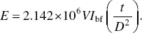
TABLE 1.6.Classes of Equipment and Typical Working Distances
Source : IEEE 1584-2018 Guide [9]. © 2002 IEEE. Also see Chapter 3.
| Classes of Equipment | Working Distance |
| 15-kV switchgear | 36 |
| 15-kV MCC | 36 |
| 5-kV switchgear | 36 |
| 5-kV switchgear | 36 |
| 5-kV MCC | 36 |
| Low voltage switchgear | 24 |
| Shallow low voltage MCCs and panel boards | 18 |
| Deep voltage MCCs and panel boards | 18 |
| Cable junction box | 18 |
TABLE 1.7.Factors for Equipment and Voltage Classes
Читать дальшеИнтервал:
Закладка:
Похожие книги на «Arc Flash Hazard Analysis and Mitigation»
Представляем Вашему вниманию похожие книги на «Arc Flash Hazard Analysis and Mitigation» списком для выбора. Мы отобрали схожую по названию и смыслу литературу в надежде предоставить читателям больше вариантов отыскать новые, интересные, ещё непрочитанные произведения.


Обсуждение, отзывы о книге «Arc Flash Hazard Analysis and Mitigation» и просто собственные мнения читателей. Оставьте ваши комментарии, напишите, что Вы думаете о произведении, его смысле или главных героях. Укажите что конкретно понравилось, а что нет, и почему Вы так считаете.