Engineering Solutions for CO2 Conversion
Здесь есть возможность читать онлайн «Engineering Solutions for CO2 Conversion» — ознакомительный отрывок электронной книги совершенно бесплатно, а после прочтения отрывка купить полную версию. В некоторых случаях можно слушать аудио, скачать через торрент в формате fb2 и присутствует краткое содержание. Жанр: unrecognised, на английском языке. Описание произведения, (предисловие) а так же отзывы посетителей доступны на портале библиотеки ЛибКат.

- Название:Engineering Solutions for CO2 Conversion
- Автор:
- Жанр:
- Год:неизвестен
- ISBN:нет данных
- Рейтинг книги:3 / 5. Голосов: 1
-
Избранное:Добавить в избранное
- Отзывы:
-
Ваша оценка:
Engineering Solutions for CO2 Conversion: краткое содержание, описание и аннотация
Предлагаем к чтению аннотацию, описание, краткое содержание или предисловие (зависит от того, что написал сам автор книги «Engineering Solutions for CO2 Conversion»). Если вы не нашли необходимую информацию о книге — напишите в комментариях, мы постараемся отыскать её.
Engineering Solutions for CO2 Conversion — читать онлайн ознакомительный отрывок
Ниже представлен текст книги, разбитый по страницам. Система сохранения места последней прочитанной страницы, позволяет с удобством читать онлайн бесплатно книгу «Engineering Solutions for CO2 Conversion», без необходимости каждый раз заново искать на чём Вы остановились. Поставьте закладку, и сможете в любой момент перейти на страницу, на которой закончили чтение.
Интервал:
Закладка:
The post‐anode CO 2capture has been extensively studied in SOFC IGCC and natural gas cycles. A simple IGFC system is similar to an IGCC system, but the gas turbine (GT) power island is replaced by a FC island. Some system configurations still have a gas or steam turbine to utilize the extra heat. “Post‐anode” CO 2capture can be applied via CO 2separation from H 2O via H 2O condensation (or via cooling, knockout, and additional drying) and can effectively result in a 100% CO 2removal. A separation system that uses condensation followed by a cascade of flash drums can be used to produce CO 2at high enough purity for pipeline transport at the SOFC anode exhaust pressure.
1.2.5.1.2 Molten Carbonate Fuel Cells (MCFCs)
The MCFC can be used to separate CO 2thanks to the functional reactions that occur inside the cell. By sending flue gas from a power plant to the cathode, the CO 2from the flue gas is selectively separated and concentrated at the anode, in a mixture of water and small amounts of unreacted hydrogen and methane. The “cleaner flue gas” is delivered to the atmosphere with up to 70% less CO 2content, which is transferred to the MCFC anode exhaust stream where it can be separated much more effectively, resulting in a high‐purity CO 2flow. The main advantage in this process is that extra power is generated because the MCFC will be fueled and operated normally to carry out the separation, and it increases the overall efficiency of the power plant and compactness of the post‐combustion unit, while reduces the energy penalty. The modularity feature of MCFC systems allows to tailor the installation to the capture needs or gradually increases the size of the capture unit.
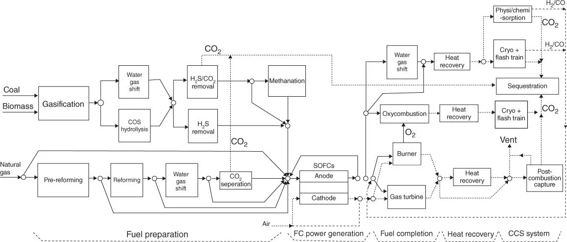
Figure 1.10Superstructure of SOFC – CO 2capture process configurations.
Source: Adams et al. [40].
One example of an MCFC and CO 2capture system was developed by Fuel Cell Energy (FCE), namely, the Combined Electric Power and Carbon‐dioxide Separation (CEPACS). In the process of capturing >90% CO 2. In this configuration, the system can generate up to 351 MWe additional power (net AC), after compensating for the auxiliary power requirements of CO 2capture and compression. 5
1.3 Integration of Post‐combustion CO 2Capture in the Power Plant and Electricity Grid
A key aspect of thermal power plants is their carbon intensity (CO 2emitted per unit of energy generated, generally expressed as kg CO 2/MWh). Nowadays, the global average is around 500 kgCO 2/MWh, which must be reduced to 100 kgCO 2/MWh by the late 2030s to be consistent with a 2 °C climate pathway [36]. Even if combined cycle thermal power plants can be considered as low carbon alternatives in some scenarios, in the mid‐to‐long term, it might be required to further decarbonize the existing units by retrofitting them with CCS or by building novel designs with low CO 2emissions. As demonstrated at commercial scale, post‐combustion CO 2capture can significantly reduce the carbon intensity of thermal power plants [2]. Table 1.3compares the carbon intensity of thermal power plants with and without CCS.
1.3.1 Integration of the Capture Unit in the Thermal Power Plant
In principle, the key integration aspects of the power plant and the capture unit are the flue gas, emitted by the power plant and sent to the capture unit, and the energy requirements of the chemical absorption/desorption process, provided by the power plant to the capture unit ( Figure 1.11). Figure 1.11 shows a simplified schematic of a power plant integrated with a post‐combustion CO 2capture system. The main energy and mass integration flows are described. Fuel and air are used in the combustion process, providing heat to produce steam in the power cycle. The flue gas from the combustion is sent to the CO 2capture unit and leaves it lean in CO 2. A CO 2rich stream is produced in the CO 2capture plant and sent to conditioning, transport, and storage. Heat in the form of steam is provided from the power plant and is returned back as water condensate. Electricity from the power plant is utilized to run the auxiliary systems of the capture unit, including the flue gas fan, cooling, and solvent circulation pumps. Higher levels of process integration between the power plant and the capture unit can be considered, as explained in [41].
Table 1.3Low heat value (LHV) efficiency, carbon intensity, and energy penalty in coal‐ and gas‐based thermal power plants with CCS [43, 54, 76].
Source: Adapted from Adams and Mac Dowell [43], Gonzalez‐Salazar et al. [54], Kvamsdal et al. [76].
| Carbon intensity (kg CO 2/MWh) | LHV efficiency (%) | Efficiency reduction (%) | |
|---|---|---|---|
| Pulverized coal subcritical | 700–1000 | 30–47 | — |
| Combined cycle | 350–450 | 56–62 | — |
| Pulverized coal with CCS at 90% capture rate | 130 | 25–42 | 5–7 |
| Combined cycle with CCS at 90% capture rate | 40–50 | 50–54 | 6–8 |
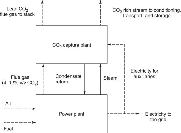
Figure 1.11Schematic integration of a power plant with a post‐combustion CO 2capture system.
The energy required to run the chemical absorption–desorption process in the capture unit process is mainly due to the (i) mechanical work to drive the flue gas fan to compensate the pressure drop induced by direct contact cooler, absorber column, and water wash sections and ducting; (ii) mechanical work to drive the pumps for cooling water and solvent circulation pumps; (iii) steam for solvent reclaiming because of its degradation in order to keep the solvent fresh and contaminant free; and (iv) steam to feed the reboiler duty: regenerate the solvent, generate stripping vapors, heat up the solvent to saturation conditions, and evaporate the water.
The flue gas is sent to the capture unit and additional pressure drop is imposed, which is a function of the thermal power plant unit, its equipment for emissions control, and the boiler type. In gas plants, the heat recovery steam generator in the exhaust gas generally imposes the additional pressure drop downstream the gas turbine (in the order of 20–40 mbar [8]), and in boilers (coal/oil/gas fired), a fan is commonly used to keep it under slightly sub‐ambient pressure. The main flue gas line equipment inducing pressure drop would be as follows [42]:
The particle removal system (electrostatic precipitator [ESP]).
The flue gas desulfurization (FGD) unit (if existing).
The NOx scrubber (if required) 2–7 mbar [42].
The bypass stack and damper if installed to bypass the capture unit.
Flue gas recirculation ducting and/or bypass (if utilized).
Direct contact cooler, absorber column, and water washes 6–80 mbar [43].
Absorber duct and stack.
In general, a fan will be required to overcome those pressure drops, whose size will depend on the volumetric flow and pressure drop. In combined cycle thermal power plants, most of the pressure drop might be overcome by raising the back pressure of the gas turbine. However, in boilers, the pressure drop is generally overcome by one or more fans [43].
The extraction of steam from the power plant steam turbine could cover the requirements in the capture system. This strategy will reduce the power output at a lower degree than the amount of heat extracted because the exergy content of the steam is just a fraction of the heat [41]. When the extracted steam is superheated (typically at higher steam pressure), it is normally cooled down by high‐pressure water injection. The heat content of the steam can be fully utilized or part of it is returned via the condensate recirculation to the power plant. The steam extraction design depends on the specific configuration and power plant unit, level of process integration, and steam requirement in the reboiler (also function of the solvent characteristics), which has been extensively discussed in the literature [44–46].
Читать дальшеИнтервал:
Закладка:
Похожие книги на «Engineering Solutions for CO2 Conversion»
Представляем Вашему вниманию похожие книги на «Engineering Solutions for CO2 Conversion» списком для выбора. Мы отобрали схожую по названию и смыслу литературу в надежде предоставить читателям больше вариантов отыскать новые, интересные, ещё непрочитанные произведения.


Обсуждение, отзывы о книге «Engineering Solutions for CO2 Conversion» и просто собственные мнения читателей. Оставьте ваши комментарии, напишите, что Вы думаете о произведении, его смысле или главных героях. Укажите что конкретно понравилось, а что нет, и почему Вы так считаете.