Heterogeneous Catalysts
Здесь есть возможность читать онлайн «Heterogeneous Catalysts» — ознакомительный отрывок электронной книги совершенно бесплатно, а после прочтения отрывка купить полную версию. В некоторых случаях можно слушать аудио, скачать через торрент в формате fb2 и присутствует краткое содержание. Жанр: unrecognised, на английском языке. Описание произведения, (предисловие) а так же отзывы посетителей доступны на портале библиотеки ЛибКат.

- Название:Heterogeneous Catalysts
- Автор:
- Жанр:
- Год:неизвестен
- ISBN:нет данных
- Рейтинг книги:4 / 5. Голосов: 1
-
Избранное:Добавить в избранное
- Отзывы:
-
Ваша оценка:
Heterogeneous Catalysts: краткое содержание, описание и аннотация
Предлагаем к чтению аннотацию, описание, краткое содержание или предисловие (зависит от того, что написал сам автор книги «Heterogeneous Catalysts»). Если вы не нашли необходимую информацию о книге — напишите в комментариях, мы постараемся отыскать её.
tate-of-the-art knowledge of heterogeneous catalysts including new applications in energy and environmental fields
This book focuses on emerging techniques in heterogeneous catalysis, from new methodology for catalysts design and synthesis, surface studies and operando spectroscopies, ab initio techniques, to critical catalytic systems as relevant to energy and the environment. It provides the vision of addressing the foreseeable knowledge gap unfilled by classical knowledge in the field.
Heterogeneous Catalysts: Advanced Design, Characterization and Applications
Presents recent developments in heterogeneous catalysis with emphasis on new fundamentals and emerging techniques Offers a comprehensive look at the important aspects of heterogeneous catalysis Provides an applications-oriented, bottoms-up approach to a high-interest subject that plays a vital role in industry and is widely applied in areas related to energy and environment
is an important book for catalytic chemists, materials scientists, surface chemists, physical chemists, inorganic chemists, chemical engineers, and other professionals working in the chemical industry.
Heterogeneous Catalysts — читать онлайн ознакомительный отрывок
Ниже представлен текст книги, разбитый по страницам. Система сохранения места последней прочитанной страницы, позволяет с удобством читать онлайн бесплатно книгу «Heterogeneous Catalysts», без необходимости каждый раз заново искать на чём Вы остановились. Поставьте закладку, и сможете в любой момент перейти на страницу, на которой закончили чтение.
Интервал:
Закладка:
3.2.2 Cathodic Electrodeposition
Cathodic electrodeposition is another well‐established electrochemical method in fabricating thin films of nanocrystalline metals, alloys, and composite catalysts, where instead of forming the desired oxide layer on the anode as demonstrated in the previous section of anodization method, the targeted materials are now deposited on the cathode through electroreduction of metal cations dissolved in the electrochemical bath. The electrochemical configuration is as shown in Figure 3.1, where precise control over the thickness and composition of the catalyst layer can be achieved either through the control of applied voltage (potentiostatic method) or current (galvanostatic method). It is a low‐temperature synthesis that is typically performed at ambient temperature.
The potentials needed to drive the reduction of metallic cations depend on the redox potential of such targeted metal. In electrodeposition of more than mono‐component, the element with positive reduction potentials will be reduced first as it can receive electrons relatively easier, although the reduction kinetics can be different. However, in principle, a convenient scanning of cathodic voltage over a window of voltage would be sufficient to identify the required potentials.
Electrodeposition is considered a strong method of coating because of their abrasion resistance, hardness, coating adhesion, and corrosion resistance. Furthermore, modulation of the abovementioned properties can be performed through a number of experimental variations including temperature of medium, precursors' concentration, pH of electrolyte, and current density. The higher thickness of coating can also be achieved by simply lengthening the duration of deposition. Because it follows the Faraday's law for electrolysis, a deposited metal (Met) started from its cations (Met z+) under constant current density ( I ) should follow this relationship:
(3.3) 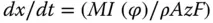
where x is the film thickness, M is the molar weight of materials, ( φ ) is current efficiency, ρ is density of the layer, A is deposited space, z is the number of transferred electrons, and F is the Faraday constant. Assuming current efficiency to be 100% with a known current density and knowing the electrode ambience, the film thickness can be established by deposition time. From an engineering perspective, cathodic electrodeposition is extremely versatile and flexible because there are many different metals, alloys, and composites that can be readily deposited in a variety of forms of thin film (e.g. coatings and freestanding sheet).
3.2.2.1 Pulse Electrodeposition
Besides the conventional direct current (DC) electrodeposition as discussed above, pulse current (PC) and pulse reverse current (PRC) methods are other modes of electrodeposition that are found useful in yielding nanostructured thin films with enhanced features. Figure 3.5depicts the modulation of pulse condition in conventional direct current electrodeposition (non‐pulse), PC, and PRC electrodeposition methods. Empowered by modern electronics and microprocessor, applied current waveform can be conveniently introduced. PC and PRC are among the most typical waveforms generated. In PC, cathodic pulse is followed by a period of time without current, while cathodic pulses followed by anodic pulses are defined as PRC. In terms of advantages in the resultant deposits, in brief, PC method affords a more compact deposit with fewer defects of pores or cracks, while PRC method can decrease internal stresses of the deposits. The technical details and advantages PC and PRC over direct current and the relationships of the deposit properties to the pulsing parameters such as frequency and current distribution have been reported previously [28]. Example of catalytic thin films made by pulse technique includes a low loading and evenly distributed Pt–Co cathode catalyst on a Nafion‐bound carbon layer [29]. The pulse‐deposited Pt–Co catalysts are homogeneously coated on the carbon electrode at a thickness of around 6 μm, four times thinner than conventional Pt–C, and were found to improve proton‐exchange membrane fuel cell (PEMFC) performance. Another noticeable feature of pulse electrodeposition is its ability to yield a conformal coating on nanostructured substrate. The emerging use of 1D nanotube or nanorod thin film has introduced new challenge in the coating of such an uneven surface at microscopic scale. Conventional direct current method always results in a solid layer electrodeposited on top of the nanotubular layer without penetration into the bottom region of the nanotubes. The limitation in conformal coating by normal direct current is due to the rapid reduction of the metallic cations at the surface (or entrance) of the nanotube/nanorod arrays. The resultant deposit formed initially on the top region continues to grow and eventually blocks the subsequent reduction of cations. Introduction of PC in the deposition involving nanotube/nanorods overcomes this weakness. During cathodic pulse, metallic cations are reduced on the surface of nanotubular substrate, while the following zero‐current pulse allows the relaxation of the deposition that allows the fresh precursor to diffuse into the deeper region of such nanostructure for the subsequent cathodic pulse. The repeating deposition and relaxation cycles eventually allow the entire surface of nanotube/nanorod to be deposited by the target metals from the top to the bottom region [30–32]. Conformal coating of nanostructured catalytic thin film is a critical aspect. When the catalytic active material is not stable in the reaction medium (e.g. the catalyst will go through chemical or photo‐dissolution during reaction), the conformal coating helps to suppress or avoid this deactivation challenge by providing a conformal protective layer. Cuprous oxide and zinc oxide are examples of unstable catalytic materials. Pulse electrodeposition of protective layers on the nanostructures of cuprous oxide and zinc oxide has been found useful in extending their usable lifetime.
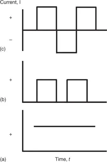
Figure 3.5 Different modes of current density for electrodeposition (a) direct current (DC), (b) pulse current (PC), and (c) pulse reverse current (PRC).
3.2.3 Electrophoretic Deposition
The term “electrodeposition” is sometimes misused in representing the electrophoretic deposition as both processes involve the use of applied direct current. Electrodeposition is based on solution of ionic species, and the deposition is achieved when ionic reduction occurs. Electrophoretic deposition, on the other hand, is a colloidal processing method in which a suspension of particles in a solvent is used. The deposition is driven by the attraction (or repulsion) of charged particles to the charged electrodes using galvanostatic or potentiostatic condition. Both positively and negatively charged colloidal particles can be deposited using electrophoretic method. For positively charged particles, they are attracted to the negatively charged electrode (cathode), and there the deposition occurs on the cathode. This process is called cathodic electrophoretic deposition. Vice versa, when deposition of negatively charged particles takes place at positively charge electrode (anode), anodic electrophoretic deposition is the term. As the readers can imagine, if the surface charge on the particles can be tuned into positive or negative region, which is feasible by suitable surface modification, the particles can be deposited using either cathodic or anodic electrophoretic deposition. Figure 3.6shows the schematic illustration of the two electrophoretic deposition processes.
Читать дальшеИнтервал:
Закладка:
Похожие книги на «Heterogeneous Catalysts»
Представляем Вашему вниманию похожие книги на «Heterogeneous Catalysts» списком для выбора. Мы отобрали схожую по названию и смыслу литературу в надежде предоставить читателям больше вариантов отыскать новые, интересные, ещё непрочитанные произведения.

Обсуждение, отзывы о книге «Heterogeneous Catalysts» и просто собственные мнения читателей. Оставьте ваши комментарии, напишите, что Вы думаете о произведении, его смысле или главных героях. Укажите что конкретно понравилось, а что нет, и почему Вы так считаете.