Electrical and Electronic Devices, Circuits, and Materials
Здесь есть возможность читать онлайн «Electrical and Electronic Devices, Circuits, and Materials» — ознакомительный отрывок электронной книги совершенно бесплатно, а после прочтения отрывка купить полную версию. В некоторых случаях можно слушать аудио, скачать через торрент в формате fb2 и присутствует краткое содержание. Жанр: unrecognised, на английском языке. Описание произведения, (предисловие) а так же отзывы посетителей доступны на портале библиотеки ЛибКат.
- Название:Electrical and Electronic Devices, Circuits, and Materials
- Автор:
- Жанр:
- Год:неизвестен
- ISBN:нет данных
- Рейтинг книги:3 / 5. Голосов: 1
-
Избранное:Добавить в избранное
- Отзывы:
-
Ваша оценка:
Electrical and Electronic Devices, Circuits, and Materials: краткое содержание, описание и аннотация
Предлагаем к чтению аннотацию, описание, краткое содержание или предисловие (зависит от того, что написал сам автор книги «Electrical and Electronic Devices, Circuits, and Materials»). Если вы не нашли необходимую информацию о книге — напишите в комментариях, мы постараемся отыскать её.
This outstanding new volume presents the basic concepts and fundamentals behind devices, circuits, and systems. It is a valuable reference for the veteran engineer and a learning tool for the student, the practicing engineer, or an engineer from another field crossing over into electrical engineering. It is a must-have for any library.
Electrical and Electronic Devices, Circuits, and Materials — читать онлайн ознакомительный отрывок
Ниже представлен текст книги, разбитый по страницам. Система сохранения места последней прочитанной страницы, позволяет с удобством читать онлайн бесплатно книгу «Electrical and Electronic Devices, Circuits, and Materials», без необходимости каждый раз заново искать на чём Вы остановились. Поставьте закладку, и сможете в любой момент перейти на страницу, на которой закончили чтение.
Интервал:
Закладка:
4.3.2 Design of Hairpin Bandpass Filter with Fractal DGS
As discussed in an earlier section, fractal DGS has become popular to reduce size and to improve the return loss. After designing hairpin bandpass filter, fractal DGS geometry is added in the ground plane to reduce the size of the filter. Two fractal hexagonal shapes connected with vertical rode as shown in Figure 4.4are etched in the ground plane. Here, 3 rditeration hexagonal fractal shape is used for better results.
Simulated result of the hairpin bandpass filter with fractal DGS is shown in Figure 4.5. Figure 4.5 (a)shows that center frequency is shifted towards lower side to 3.16 GHz. Response shifting in the lower frequency range indicates size reduction. Insertion loss in the case of fractal DGS filter is 1.93 dB, which is more compared to filter without fractal DGS (0.41 dB). The 3-dB bandwidth of the filter is 530 MHz. Similarly, as per Figure 4.5 (b)the resonance frequency is shifted towards the left side and return loss in fractal DGS filter is 39 dB, which is improved compared to hairpin bandpass filter without fractal DGS. Figures 4.6 (a)and (b)show a comparison of S 21and S 11of hairpin bandpass filter and hairpin bandpass filter with fractal DGS, respectively. Comparing the result, it is observed that shifting of the center/resonant frequency to lower side and return loss improvement for a filter with fractal DGS.
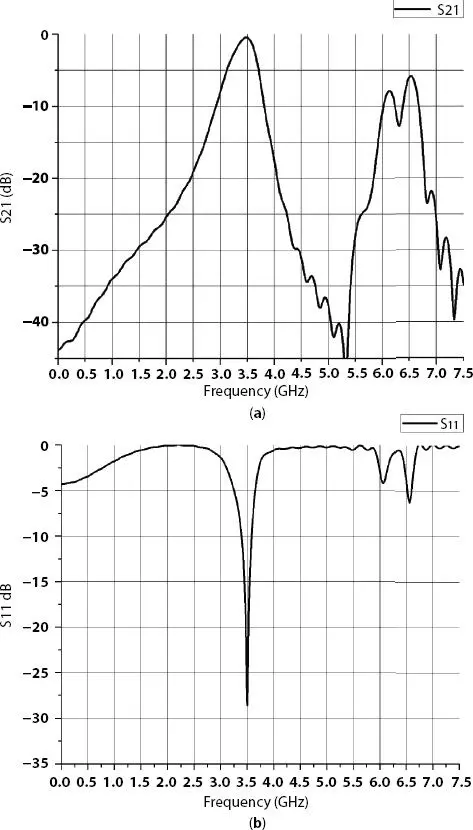
Figure 4.3 (a) S 21and (b) S 11of hairpin bandpass filter.
Fabricated hairpin bandpass filter with fractal DGS is tested with Anritsu MS2307C Vector Network Analyzer (VNA). Before testing, SOLT calibration was performed for the VNA. Figure 4.7shows hairpin filter with Fractal DGS under test. The measurement results are shown for S 21and S 11of hairpin filter with the fractal DGS in Figure 4.8 (a)and Figure 4.8 (b).
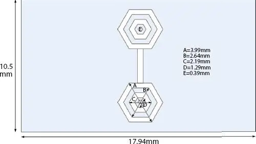
Figure 4.4 Fractal DGS (Back/GND) portion of hairpin bandpass filter.
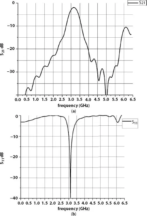
Figure 4.5 Simulated return loss characteristics (a) S 21and (b) S 11of haripin bandpass filter with fractal DGS.
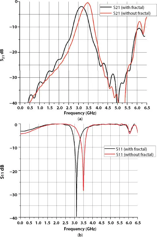
Figure 4.6 Comparison of simulated response (a)S 21(b) S 11of bandpass filter with fractal DGS and without fractal DGS.
It can be seen from Figure 4.8 (a)S 21and (b) S 11that simulated and measured result matches with each other that verifies our design. Minor mismatch is observed in S 21and S 11of the measured results because of fabrication error, dielectric tolerance of the substrate, soldering error, etc.
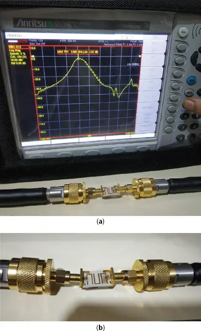
Figure 4.7 Testing/measurement of fabricated hairpin bandpass filter with fractal DGS (a) S 21measurement setup with VNA (b) Enlarge view of setup.
4.3.3 Design of Tunable Hairpin Bandpass Filter with Fractal DGS
To make a filter tunable, varactor diode or PIN diode has to be incorporated in the design. Here, two varactor diodes are inserted in outer hexagonal of fractal DGS as shown in Figure 4.9. For simulation purpose in CST MICROWAVE STUDIO ®V. 2018, R-L-C components are chosen. To consider a perfect capacitor, R = 0 Ω, L = 0 H and desired values of C is selected using parametric sweep.
By using parametric sweep in simulation, various values of C (treated as varactor diode) were applied and simulation results are shown in Figures 4.10and 4.11. As it is observed from the response, the center frequency of the band can be varied from 3.3 GHz to 3.58 GHz by changing values of C from 20 pf to 1.5 pf. As center frequency varies, variation in bandwidth is also observed from 360 MHz to 530 MHz. Tuning of center frequency is not much above 8 pf of capacitance value. For better visibility, magnified view of S 21is shown in Figure 4.10(b)and magnified view of S 11is shown in Figure 4.11(b). Also it is observed that insertion loss is minimized during the tuning range; it varies from 0.44 to 0.79 dB. Proposed filter is low insertion loss and a very compact filter. In S 11response, return loss stays around 20 dB to 25 dB, which is expected for any filter.
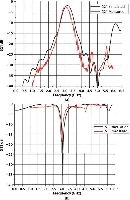
Figure 4.8 Comparison of simulated and measured result (a) S 21and (b) S 11of hairpin bandpass filter with fractal DGS.
Table 4.2 shows comparison of center frequency, bandwidth and insertion loss. As per simulation work, it is concluded that fractal DGS helps to make filter design compact.
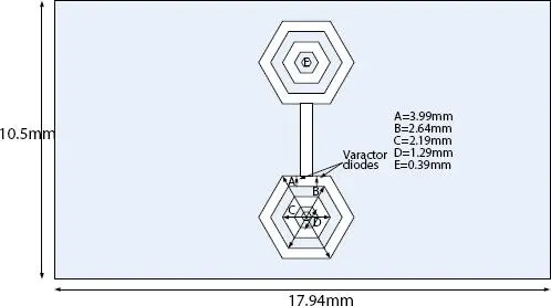
Figure 4.9 Hairpin bandpass filter with fractal DGS with varactor diodes.
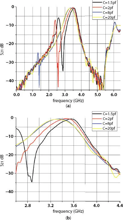
Figure 4.10 (a) S 21of tunable hairpin bandpass filter with fractal DGS (b) magnified version of Figure
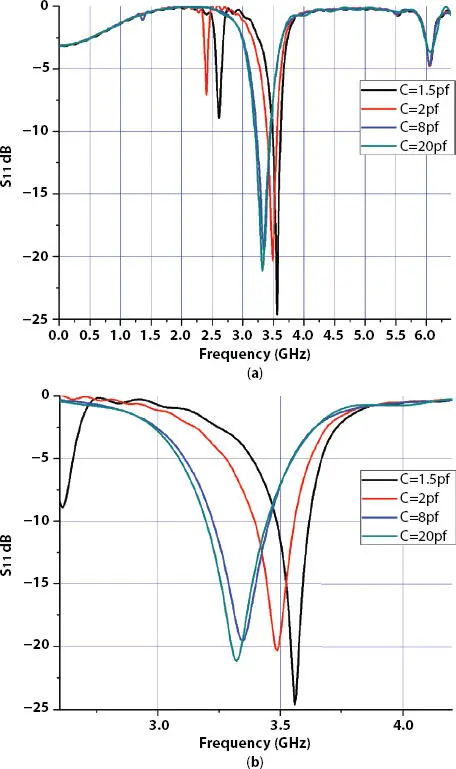
Figure 4.11 (a) S 11of tunable hairpin bandpass filter with fractal DGS (b) magnified version of Figure
Table 4.2Parametric comparison of simulated work.
| Filter | Center Frequency (GHz) | Bandwidth (MHz) | Insertion loss (dB) |
| Hairpin bandpass filter | 3.48 | 430 | 0.41 |
| Hairpin bandpass filter with fractal DGS | 3.16 | 530 | 1.93 |
| Tunable Hairpin bandpass filter with fractal DGS | 3.31-3.55 | 360 to 530 | 0.44 to 0.79 |
4.4 Conclusion
The hairpin bandpass filter offers compactness and good return loss. The proposed work of a hairpin filter with fractal DGS shifts the resonant frequency to lower frequencies, which reduces the size of the filter. Tunability along with hexagonal fractal DGS is achieved by using variable capacitance (varactor diode) inserted in fractal DGS. The simulation work shows that the proposed filter has a compact size and much less insertion loss.
Acknowledgement
The authors are thankful to ELARC Lab at Birla Vishwakarma MahaVidyalaya, V V Nagar, Gujarat, India, for providing the measurement facility.
References
1. Z. Awang (2014), Microwave systems design , vol. 9789814451246. Springer Singapore.
Читать дальшеИнтервал:
Закладка:
Похожие книги на «Electrical and Electronic Devices, Circuits, and Materials»
Представляем Вашему вниманию похожие книги на «Electrical and Electronic Devices, Circuits, and Materials» списком для выбора. Мы отобрали схожую по названию и смыслу литературу в надежде предоставить читателям больше вариантов отыскать новые, интересные, ещё непрочитанные произведения.


Обсуждение, отзывы о книге «Electrical and Electronic Devices, Circuits, and Materials» и просто собственные мнения читателей. Оставьте ваши комментарии, напишите, что Вы думаете о произведении, его смысле или главных героях. Укажите что конкретно понравилось, а что нет, и почему Вы так считаете.