Michael Graham - Wind Energy Handbook
Здесь есть возможность читать онлайн «Michael Graham - Wind Energy Handbook» — ознакомительный отрывок электронной книги совершенно бесплатно, а после прочтения отрывка купить полную версию. В некоторых случаях можно слушать аудио, скачать через торрент в формате fb2 и присутствует краткое содержание. Жанр: unrecognised, на английском языке. Описание произведения, (предисловие) а так же отзывы посетителей доступны на портале библиотеки ЛибКат.

- Название:Wind Energy Handbook
- Автор:
- Жанр:
- Год:неизвестен
- ISBN:нет данных
- Рейтинг книги:3 / 5. Голосов: 1
-
Избранное:Добавить в избранное
- Отзывы:
-
Ваша оценка:
Wind Energy Handbook: краткое содержание, описание и аннотация
Предлагаем к чтению аннотацию, описание, краткое содержание или предисловие (зависит от того, что написал сам автор книги «Wind Energy Handbook»). Если вы не нашли необходимую информацию о книге — напишите в комментариях, мы постараемся отыскать её.
delivers a fully updated treatment of key developments in wind technology since the publication of the book’s Second Edition in 2011. The criticality of wakes within wind farms is addressed by the addition of an entirely new chapter on wake effects, including ‘engineering’ wake models and wake control. Offshore, attention is focused for the first time on the design of floating support structures, and the new ‘PISA’ method for monopile geotechnical design is introduced.
The coverage of blade design has been completely rewritten, with an expanded description of laminate fatigue properties and new sections on manufacturing methods, blade testing, leading-edge erosion and bend-twist coupling. These are complemented by new sections on blade add-ons and noise in the aerodynamics chapters, which now also include a description of the Leishman-Beddoes dynamic stall model and an extended introduction to Computational Fluid Dynamics analysis.
The importance of the environmental impact of wind farms both on- and offshore is recognised by extended coverage, which encompasses the requirements of the Grid Codes to ensure wind energy plays its full role in the power system. The conceptual design chapter has been extended to include a number of novel concepts, including low induction rotors, multiple rotor structures, superconducting generators and magnetic gearboxes.
References and further reading resources are included throughout the book and have been updated to cover the latest literature. Importantly, the core subjects constituting the essential background to wind turbine and wind farm design are covered, as in previous editions. These include:
The nature of the wind resource, including geographical variation, synoptic and diurnal variations and turbulence characteristics The aerodynamics of horizontal axis wind turbines, including the actuator disc concept, rotor disc theory, the vortex cylinder model of the actuator disc and the Blade-Element/Momentum theory Design loads for horizontal axis wind turbines, including the prescriptions of international standards Alternative machine architectures The design of key components Wind turbine controller design for fixed and variable speed machines The integration of wind farms into the electrical power system Wind farm design, siting constraints and the assessment of environmental impact Perfect for engineers and scientists learning about wind turbine technology, the
will also earn a place in the libraries of graduate students taking courses on wind turbines and wind energy, as well as industry professionals whose work requires a deep understanding of wind energy technology.
Wind Energy Handbook — читать онлайн ознакомительный отрывок
Ниже представлен текст книги, разбитый по страницам. Система сохранения места последней прочитанной страницы, позволяет с удобством читать онлайн бесплатно книгу «Wind Energy Handbook», без необходимости каждый раз заново искать на чём Вы остановились. Поставьте закладку, и сможете в любой момент перейти на страницу, на которой закончили чтение.
Интервал:
Закладка:
In the current context, the effects of drag are dependent upon the magnitude of the lift/drag ratio, which, in turn, depends on the aerofoil profile but largely on Reynolds number and on the surface roughness of the blade. A high value of lift/drag ratio would be about 150, whereas a low value would be about 40.
Unfortunately, with the inclusion of drag, the algebra of the analysis is complex. Polynomial equations have to be solved for both a and a ′. The details of the analysis are left for the reader to discover.
In the presence of drag, the axial flow induction factor for optimal operation is not uniform over the disc because it is in the hypothetical drag‐free situation. However, the departure of the axial flow distribution from uniformity is not great, even when the lift/drag ratio is low, provided the flow around a blade remains attached.
The radial variation of the axial and tangential flow induction factors is shown in Figure 3.23for zero drag and for a lift/drag ratio of 40. The tangential flow induction factor is lower in the presence of drag than without because the blade drags the fluid around in the direction of rotation, opposing the general rotational reaction to the shaft torque.
From the torque/angular momentum Eq. (3.52), the blade geometry parameter becomes
(3.76) 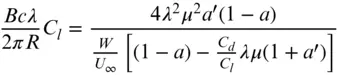
Figure 3.24compares the blade geometry parameter distributions for zero drag and a lift/drag ratio of 40, and, as is evident, drag has very little effect on blade optimal design.
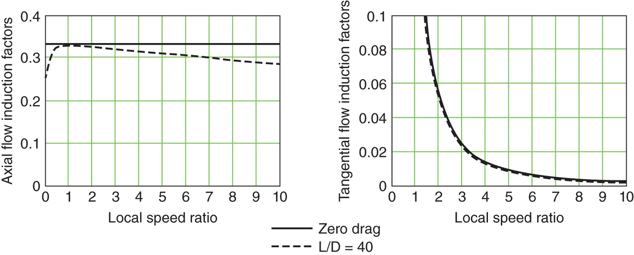
Figure 3.23 Radial variation of the flow induction factors with and without drag.
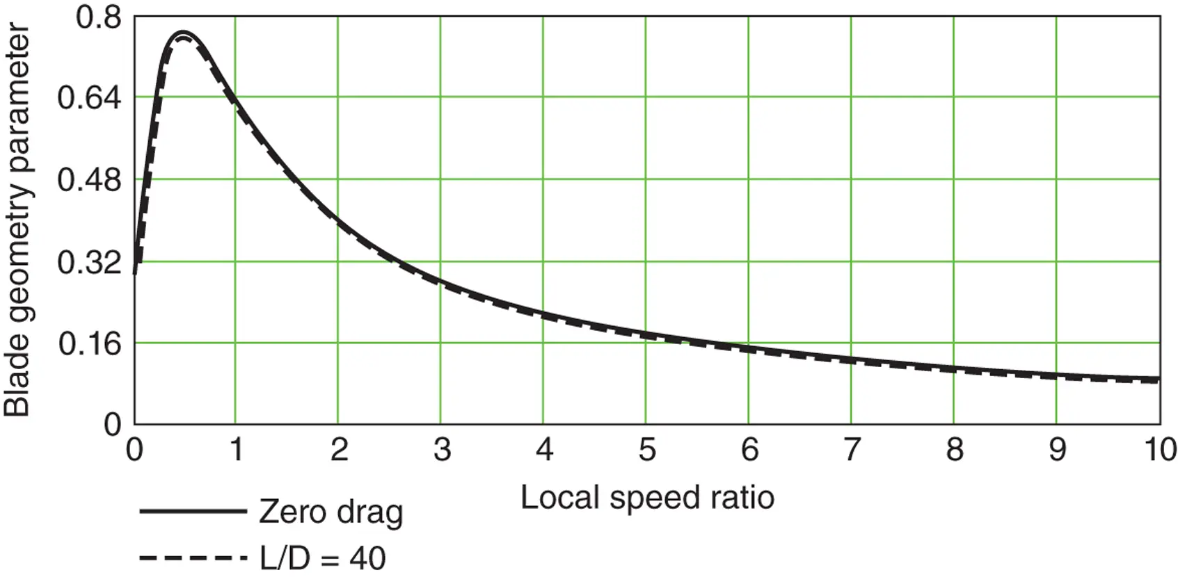
Figure 3.24 Spanwise variation of the blade geometry parameter with and without drag.
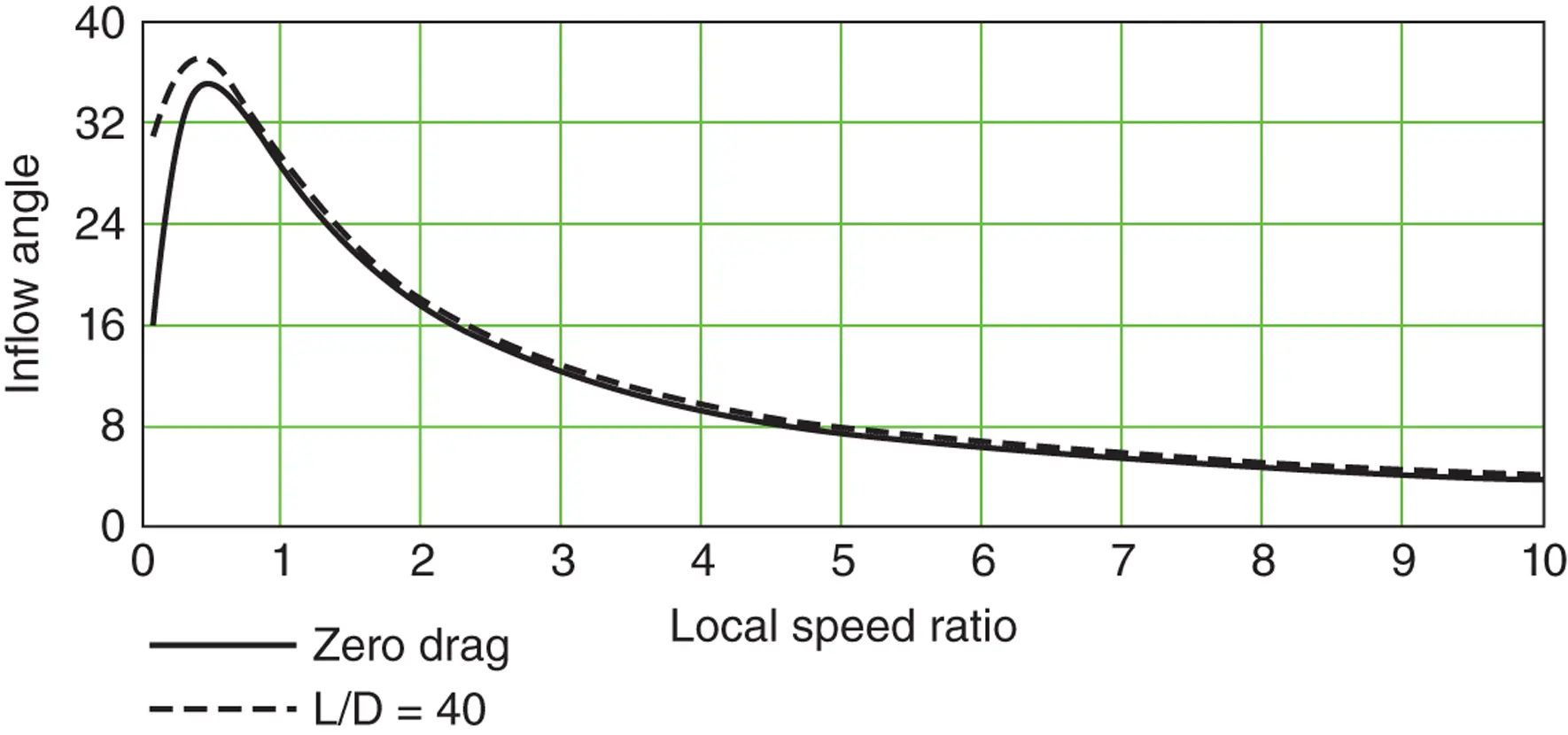
Figure 3.25 Variation of inflow angle with local speed ratio with and without drag.
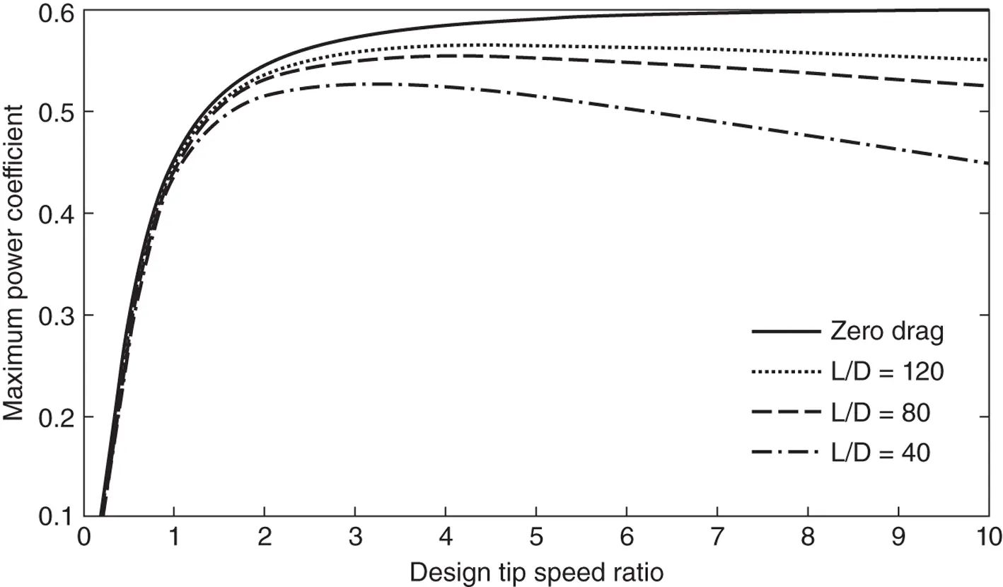
Figure 3.26 The variation of maximum C Pwith design λ for various lift/drag ratios.
A similar result is apparent for the inflow angle distribution ( Figure 3.25), in which drag is also seen to have little influence.
As far as blade design for optimal operation is concerned, drag can be ignored, greatly simplifying the process.
The results of Eq. (3.57)show that the maximum power coefficients for a range of design tip speed ratios and several lift/drag ratios are as shown in Figure 3.26. The flow induction factors have been determined without drag using Eqs. (3.54a)and (3.55), but the torque has been calculated using Eq. (3.57), which includes drag. The losses caused by drag are significant and increase with increasing design tip speed ratio. As will be shown later, when tip‐losses are also taken into account, the losses at low tip speed ratios are even greater.
3.8.5 Optimal blade design for constant‐speed operation
If the rotational speed of a turbine is maintained at a constant level, then the tip speed ratio is continuously changing, and a blade optimised for a fixed tip speed ratio would not be appropriate. Closed‐form solutions have been derived for optimum wind turbines; see Peters and Modarres (2013) and Jamieson (2018).
No simple technique is available for the optimal design of a blade operating at constant rotational speed. Non‐linear (numerical) optimisation techniques may be used to solve the problem of maximising energy capture at a given site incorporating the data on its specific wind speed distribution. Alternatively, a design tip speed ratio can be chosen corresponding to the wind speed at the specified site that contains the most energy, or, more practically, the pitch angle for the whole blade can be adjusted to maximise energy capture.
3.9 The effects of a discrete number of blades
3.9.1 Introduction
The analysis described in all prior sections assumes that the rotor has an infinite number of blades of infinitesimal chord so that every fluid particle passing through the rotor disc passes close to a blade through a region of strong interaction, i.e. that the loss of momentum in any annulus is uniform with respect to azimuth angle θ. With a finite (usually small, two or three) number of blades, some fluid particles will interact more strongly with the blades and some less strongly. The immediate loss of (kinetic) momentum by a particle will depend on the distance between its streamline and the blade as the particle passes through the rotor disc. These differences are subsequently reduced but not eliminated by the action of pressure forces between the adjacent curved streamlines and eventually by mixing. The axial induced velocity will therefore vary around the disc, the average value determining the overall axial momentum of the flow. What is also relevant is the incident velocity (relative angle and speed) that each blade section senses, i.e. to which it responds, as it rotates. When as here the incident flow is not uniform, a blade section senses a weighted average of the flow induced in the region occupied by the section in the absence of its own self‐generated flow field. This is usually evaluated as the velocity at the quarter chord of the section (cf. lifting line theory). For a rotor for which the product σλ of solidity and tip speed ratio is not too small, as is usual, it is found that the combination of incident wind, average axial induced velocity, and blade rotation speed gives a very good approximation to this incident velocity except close to the tip and root ends of the blade, where the sectional approximation breaks down.
3.9.2 Tip‐losses
Where the axial flow induction factor a becomes large at the blade position, then, by Eqs. (3.44), the inflow angle ϕ will reduce, and for a given pitch angle the angle of attack α and hence the lift force will become small. At the tip the lift force must decrease to zero because the blade surface pressures must be continuous around the tip. The component of the lift force in the tangential direction in the tip region will therefore be small and so will be its contribution to the torque. A reduced torque means reduced power, and this reduction is known as tip‐loss because the effect occurs at the outermost parts of the blades. A similar effect occurs for the same reason at the blade root but being at small radius has much less effect on torque and power.
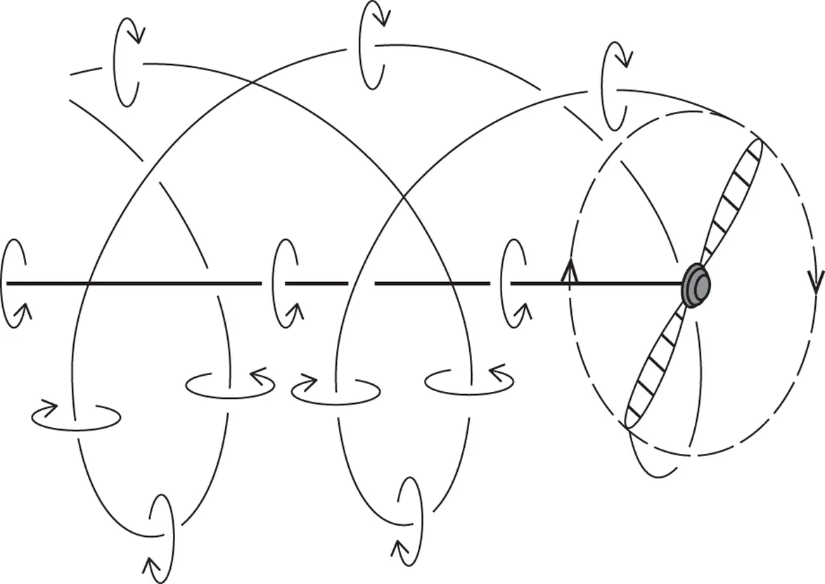
Figure 3.27 Helical trailing tip vortices of a horizontal axis turbine wake.
To account for tip‐losses, the manner in which the axial flow induction factor varies azimuthally needs to be known, but, unfortunately, this requirement is beyond the abilities of the BEM theory.
Читать дальшеИнтервал:
Закладка:
Похожие книги на «Wind Energy Handbook»
Представляем Вашему вниманию похожие книги на «Wind Energy Handbook» списком для выбора. Мы отобрали схожую по названию и смыслу литературу в надежде предоставить читателям больше вариантов отыскать новые, интересные, ещё непрочитанные произведения.


Обсуждение, отзывы о книге «Wind Energy Handbook» и просто собственные мнения читателей. Оставьте ваши комментарии, напишите, что Вы думаете о произведении, его смысле или главных героях. Укажите что конкретно понравилось, а что нет, и почему Вы так считаете.