Rajib Taid - Mobile Communications Systems Development
Здесь есть возможность читать онлайн «Rajib Taid - Mobile Communications Systems Development» — ознакомительный отрывок электронной книги совершенно бесплатно, а после прочтения отрывка купить полную версию. В некоторых случаях можно слушать аудио, скачать через торрент в формате fb2 и присутствует краткое содержание. Жанр: unrecognised, на английском языке. Описание произведения, (предисловие) а так же отзывы посетителей доступны на портале библиотеки ЛибКат.

- Название:Mobile Communications Systems Development
- Автор:
- Жанр:
- Год:неизвестен
- ISBN:нет данных
- Рейтинг книги:5 / 5. Голосов: 1
-
Избранное:Добавить в избранное
- Отзывы:
-
Ваша оценка:
Mobile Communications Systems Development: краткое содержание, описание и аннотация
Предлагаем к чтению аннотацию, описание, краткое содержание или предисловие (зависит от того, что написал сам автор книги «Mobile Communications Systems Development»). Если вы не нашли необходимую информацию о книге — напишите в комментариях, мы постараемся отыскать её.
Mobile Communications Systems Development: A Practical Approach for System Understanding, Implementation and Deployment In-depth chapters cover the entire protocol stack from the Physical (PHY) to the Application layer, discuss theoretical and practical considerations, and describe software implementation based on the 3GPP standardized technical specifications. The book includes figures, tables, and sample computer code to help readers thoroughly comprehend the functions and underlying concepts of a mobile communications network. Each chapter includes an introduction to the topic and a chapter summary. A full list of references, and a set of exercises are also provided at the end of the book to test comprehension and strengthen understanding of the material. Written by a respected professional with more than 20 years’ experience in the field, this highly practical guide:
Provides detailed introductory information on GSM, GPRS, UMTS, and LTE mobile communications systems and networks Describes the various aspects and areas of the LTE system air interface and its protocol layers Covers troubleshooting and resolution of mobile communications systems and networks issues Discusses the software and hardware platforms used for the development of mobile communications systems network elements Includes 5G use cases, enablers, and architectures that cover the 5G NR (New Radio) and 5G Core Network
is perfect for graduate and postdoctoral students studying mobile communications and telecom design, electronic engineering undergraduate students in their final year, research and development engineers, and network operation and maintenance personnel.
Mobile Communications Systems Development — читать онлайн ознакомительный отрывок
Ниже представлен текст книги, разбитый по страницам. Система сохранения места последней прочитанной страницы, позволяет с удобством читать онлайн бесплатно книгу «Mobile Communications Systems Development», без необходимости каждый раз заново искать на чём Вы остановились. Поставьте закладку, и сможете в любой момент перейти на страницу, на которой закончили чтение.
Интервал:
Закладка:
A 3GPP technical specification may cover the description of GSM, GPRS, UMTS, LTE, and 5G system protocol functions and procedures. A method to identify the functions and procedures description that applies to a particular communications system was presented. Finally, the reader is recommended to focus on a particular logical interface, protocol stack at a time, and its specifications as mentioned in the references section and then, proceed gradually toward other logical interfaces and their protocol stack.
4 Encoding and Decoding of Messages
Introduction
This chapter covers the methods for encoding and decoding of control plane or signaling messages and protocol data units (PDUs) that are exchanged between the peer protocols layers of network elements of mobile communications networks, from the Global System for Mobile Communication (GSM) to the 5G system. The method of a description of signaling messages and their encoding and decoding is part of a protocol layer specification, which differs from one logical interface to another one. Messages are exchanged between the network elements of a mobile communications network to facilitate various communication services to users. A source network element creates a protocol layer message in a predefined format using a particular encoding/packing method and sends it to the peer network element over the concerned logical interface. The peer network element decodes or unpacks a message using the same method that was used to encode it.
We begin with the description of encoding and decoding methods of air interface Layer 3 signaling messages, followed by the Layer 2 signaling messages exchanged between a Mobile station (MS)/User Equipment (UE) and the network. We also cover the encoding method used by the Radio Access Network (RAN) and core network (CN) elements. We close this chapter with the method of embedding a control plane message within another control plane message to reduce signaling overhead between two network elements, especially over the air interface.
4.1 Description and Encoding/Decoding of Air Interface Messages
One important aspect of a mobile communications network is the “ signaling message ” that is exchanged between its network elements. A signaling message is nothing but an exchange of a series of information between the network elements to establish, maintain, and release of resources allocated for communication services being provided to the service users. Information in a particular signaling message being transmitted is encoded (packed) and decoded (unpacked) differently across the mobile communications systems, i.e. from the GSM to 5G. Depending on the protocol stack and its layers supported by a network element, it may use different methods of encoding and decoding of signaling messages at each protocol layer. Also, a network element may decode the contents of a message that it receives or may not decode but transparently forward to the destination network element using another encoding method.
A protocol layer of a network element may send a signaling message to its peer layer like a long series of ordered bits where an octet alignment may or may not be required. Another protocol layer of the same network element may send a signaling message as a series of octets with octet alignments. To sum up, as far as the development of a protocol layer is concerned, two aspects of signaling messages defined in its technical specifications are required to be considered:
The method used to describe a signaling message
The method used for encoding and decoding of a signaling message to transfer/receive among network elements.
It may be noted that the method of description, i.e. tabular format, and encoding/decoding of signaling messages differs from layer to layer. In the subsequent sections that follow, the following methods of descriptions, encoding, and decoding of mobile communications networks signaling messages over their respective air interfaces are discussed.
1 Encoding and Decoding of Air Interface Layer 3 Messages
This method is used by the GSM air interface Radio Resource (RR) sublayer of Layer 3 protocol between an MS and the base station controller (BSC). This method is also used by the Call Control (CC) and Mobility Management (MM) sublayers of GSM; GPRS Mobility Management (GMM), Session Management (SM) layers of Universal Mobile Telecommunication System (UMTS); Evolved Packet System Session Management (ESM) and Evolved Packet System Mobility Management (EMM) layers of Long‐Term Evolution (LTE)/Evolved Packet System (EPS) system; and 5GMM and 5GSM layers of 5G system. These protocol layers work between an MS/UE and the CN.
1 Concrete Syntax Notation.1 (CSN.1) Encoding/Decoding
This method is used by the General Packet Radio Service (GPRS) air interface Layer 2 radio link control (RLC)/Medium Access Control (MAC) protocol between the MS and BSC.
1 Abstract Syntax Notation.1 (ASN.1) Encoding/Decoding Using Packed Encoding Rule (PER)
This method is used by the following protocol layers over their respective logical interfaces:
UMTS Radio Resource Control (RRC) air interface Layer 3 between the UE and UMTS Terrestrial Radio Access Network (UTRAN)/Radio Network Controller (RNC),
LTE RRC air interface Layer 3 between the UE and Evolved‐UMTS Terrestrial Radio Access Network (E‐UTRAN)/eNodeB, and
5G New Radio (NR) RRC air interface Layer 3 between the UE and Next Generation Radio Access Network (NG‐RAN)/5G Base Station (gNB).
4.1.1 Encoding/Decoding: Air Interface Layer 3 Messages
To describe and encode/decode the air interface Layer 3 and its sublayers signaling messages, the basic tabular form of definition is used. Except for the UMTS, LTE, and 5G RRC layers, the following layers share the same tabular format to describe their air interface Layer 3 and Non‐access Stratum (NAS) layers messages.
GSM RR, MM, and Connection Management (CM) layers,
GPRS/UMTS GMM and SM layers,
LTE/EPS NAS layers – EMM and ESM NAS, and
5G System NAS layers – 5GMM and 5GSM.
An air interface Layer 3/NAS layers signaling message consists of an ordered series of octets (1 octet: 8 bits) and each message being with a protocol header. The protocol header is followed by protocol information fields. Each field is known as the information element (IE). An IE has certain attributes such as its unique identifier and presence requirements in the message, length, and value as described below. IEs and their attributes are described in a tabular format.
IE and its Identifier
A signaling message carries various information from a sender to a receiver through a collection of IEs . Each IE indicates particular information of a protocol layer to a receiver and is uniquely identified by a so‐called Information Element Identifier (IEI). An IE has a name and is represented by assigning a hexadecimal value through the IEI. IEs of a signaling message may have different lengths such as 1 octet, 2 octets, and so on. An IE of a message has the following components, also shown graphically in Figure 4.1.
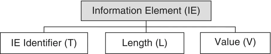
Figure 4.1 Components of an IE of a protocol message.
Type (T), represented by the IEI,
Length (L), in octets, and
Value (V), i.e. an actual value of an IE.
Presence Requirements of IE
The presence of an IE in a signaling message may not be required always. Based on this, the presence of an IE is classified as shown in Figure 4.2:
Mandatory (M) – An IE must be present always; if it is not, the receiver will consider the message as an erroneous one and reports a protocol error.
Читать дальшеИнтервал:
Закладка:
Похожие книги на «Mobile Communications Systems Development»
Представляем Вашему вниманию похожие книги на «Mobile Communications Systems Development» списком для выбора. Мы отобрали схожую по названию и смыслу литературу в надежде предоставить читателям больше вариантов отыскать новые, интересные, ещё непрочитанные произведения.


Обсуждение, отзывы о книге «Mobile Communications Systems Development» и просто собственные мнения читателей. Оставьте ваши комментарии, напишите, что Вы думаете о произведении, его смысле или главных героях. Укажите что конкретно понравилось, а что нет, и почему Вы так считаете.