Rajib Taid - Mobile Communications Systems Development
Здесь есть возможность читать онлайн «Rajib Taid - Mobile Communications Systems Development» — ознакомительный отрывок электронной книги совершенно бесплатно, а после прочтения отрывка купить полную версию. В некоторых случаях можно слушать аудио, скачать через торрент в формате fb2 и присутствует краткое содержание. Жанр: unrecognised, на английском языке. Описание произведения, (предисловие) а так же отзывы посетителей доступны на портале библиотеки ЛибКат.
- Название:Mobile Communications Systems Development
- Автор:
- Жанр:
- Год:неизвестен
- ISBN:нет данных
- Рейтинг книги:5 / 5. Голосов: 1
-
Избранное:Добавить в избранное
- Отзывы:
-
Ваша оценка:
Mobile Communications Systems Development: краткое содержание, описание и аннотация
Предлагаем к чтению аннотацию, описание, краткое содержание или предисловие (зависит от того, что написал сам автор книги «Mobile Communications Systems Development»). Если вы не нашли необходимую информацию о книге — напишите в комментариях, мы постараемся отыскать её.
Mobile Communications Systems Development: A Practical Approach for System Understanding, Implementation and Deployment In-depth chapters cover the entire protocol stack from the Physical (PHY) to the Application layer, discuss theoretical and practical considerations, and describe software implementation based on the 3GPP standardized technical specifications. The book includes figures, tables, and sample computer code to help readers thoroughly comprehend the functions and underlying concepts of a mobile communications network. Each chapter includes an introduction to the topic and a chapter summary. A full list of references, and a set of exercises are also provided at the end of the book to test comprehension and strengthen understanding of the material. Written by a respected professional with more than 20 years’ experience in the field, this highly practical guide:
Provides detailed introductory information on GSM, GPRS, UMTS, and LTE mobile communications systems and networks Describes the various aspects and areas of the LTE system air interface and its protocol layers Covers troubleshooting and resolution of mobile communications systems and networks issues Discusses the software and hardware platforms used for the development of mobile communications systems network elements Includes 5G use cases, enablers, and architectures that cover the 5G NR (New Radio) and 5G Core Network
is perfect for graduate and postdoctoral students studying mobile communications and telecom design, electronic engineering undergraduate students in their final year, research and development engineers, and network operation and maintenance personnel.
Mobile Communications Systems Development — читать онлайн ознакомительный отрывок
Ниже представлен текст книги, разбитый по страницам. Система сохранения места последней прочитанной страницы, позволяет с удобством читать онлайн бесплатно книгу «Mobile Communications Systems Development», без необходимости каждый раз заново искать на чём Вы остановились. Поставьте закладку, и сможете в любой момент перейти на страницу, на которой закончили чтение.
Интервал:
Закладка:
Air interfaces, i.e. Uu, Um, between UE/MS and RAN of GSM, UMTS, LTE, and 5G systems.
Network interfaces (A, Gb, S1, Iu, X2, Gn, NG, and so on) between the GSM, UMTS, LTE, and 5G RANs and their respective CNs.
In fact, the majority of the logical interfaces are found only in the CNs domain along with the other CN elements such as the Home Location Register/Home Subscriber Server (HLR/HSS), Visitor Location Register (VLR), and Policy Charging and Restriction Function (PCRF). Other logical interfaces are also available that can be configured to support interworking and interoperations, e.g. CS fallback, Single Radio Voice Call Continuity, and so on, between two mobile communications networks. Some of these interoperation facilities may be configured as an optional and separately licensed feature.
A developer must put the focus on a particular network element and its logical interfaces at a time. The air interface and its protocol stack is the most interesting one that consists of advanced wireless communications theories. The air interface differentiates one system from its predecessor. As a starting point, the reader is advised to go through and familiarize themselves with the list of 3GPP TSs mentioned in the Reference section of this book. There are 3GPP TSs describing the protocol layers of the respective air interface of the GSM, GPRS, UMTS, LTE, and 5G systems. The reader may, then, proceed gradually toward the other logical interfaces and their protocol stack.
3.11.1 Identifying a Logical Interface, Protocol Stack, and Its Layers
To identify and understand a particular protocol stack architecture, its layers, and their corresponding 3GPP technical specifications, the following steps may be taken:
Choose a particular mobile communications system such as the GSM, GPRS, and UMTS, LTE, or 5G as your area of interest. Use the information available in the 3GPP site [2] (second, third, fourth column) as mentioned in Section 2.5.6.
Next, decide the particular network element of interest such as GSM MS, BTS, BSC, and MSC; UMTS NodeB, and RNC; or LTE eNodeB, MME, and S‐GW or 5G gNB and 5G core.
Now, look at the logical interfaces supported by the chosen network element. Pick a particular logical interface and look at its protocol stack and layers. A logical interface and its protocol stack cover different subjects and specifications area. Look at the subject and specifications areas mentioned in the 3GPP site [2], first column, and pick a particular subject area. Against this chosen subject area, e.g. signaling, requirements, and so on, or a particular protocol layer, attempt to identify the corresponding technical specifications series and its specifications from the column 2, 3, or 4, 3GPP site [2].
Study the protocol layer architecture, its functions and procedures, and other details from the identified technical specification.
Example 3.14describes the typical steps to be used to derive the 3GPP technical specification of a protocol layer and its sub‐layer.
Figure 3.21shows the protocol stack of the A‐interface on the CN side.
Example 3.14GSM Circuit‐Switched BSS and Air Interface Layer 3 Technical Specifications
Suppose a developer is interested to study the GSM BSS that consists of BTSs and BSC network elements. Further, suppose that developer is interested in the air interface Layer 3 protocol, between an MS and the BSC, of a GSM system. Figure 3.21below shows the GSM air interface Layer 3 protocols along with its sublayer protocol, as follows:
Call Control Management (CM),
MM, and
Radio Resource Management (RR).
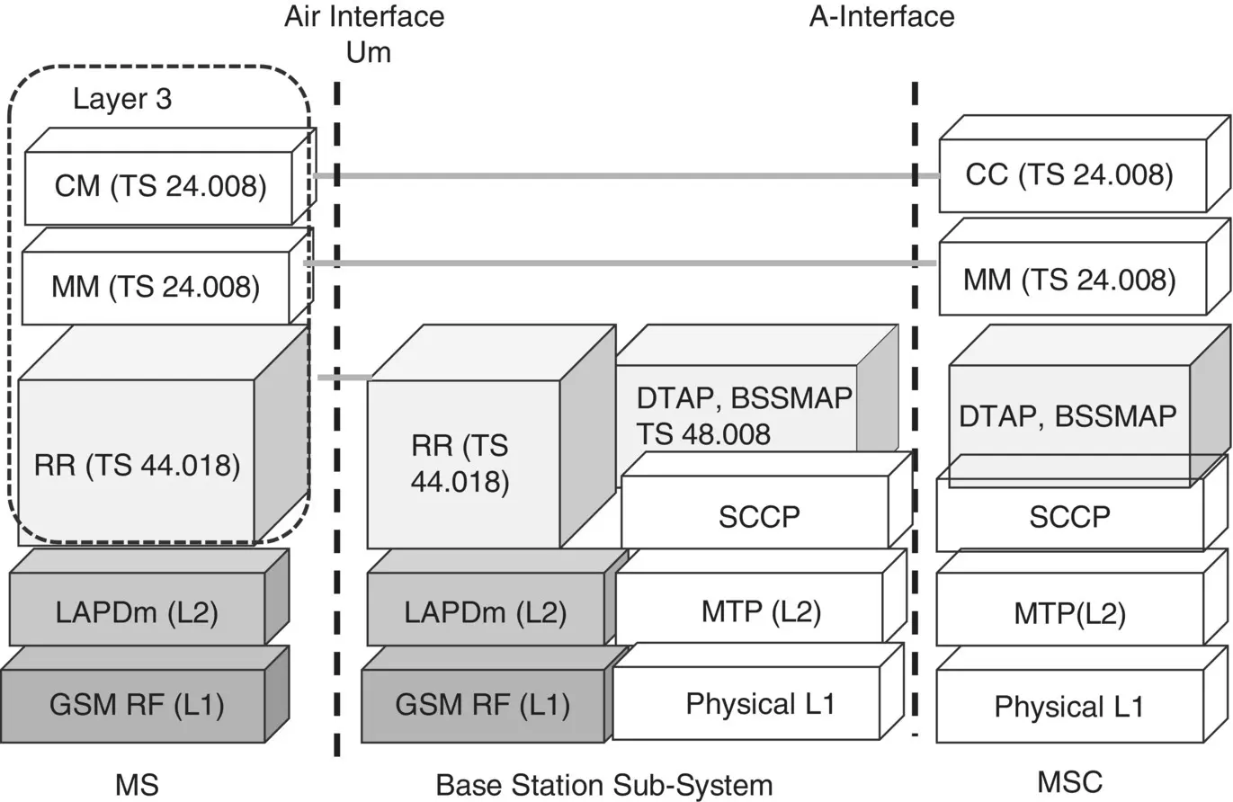
Figure 3.21 Illustration: GSM air interface Layer 3 protocol stack.
1 As shown in Figure 3.21, the GSM air interface Layer 3 consists of the CM, MM, and RR layers. The developer may be further interested in the Radio Resource Management, (RR) sublayer of the GSM Layer 3 protocol stack. The RR layer of a BSC deals with the signaling functions/messages of the GSM Layer 3 protocol stack. Now refer to the 3GPP site [2].
2 For the GSM signaling protocols/messages that are exchanged between an MS and the BSC and vice versa, the corresponding 3GPP TS series number will be either 44 Series (After Release 4, including, GSM) or 4 Series (Before Release 4 GSM). Assume that you have considered the 3GPP TS Series 44. Within this series, one will find all the technical specifications, listed in ascending order, related to signaling messages between MS and the BSC. Now, look for the technical specification having the title Radio Resource Management protocol. You got the desired TS. In this case, it is the 3GPP TS 44.018 [130]. For Series 4, the corresponding TS will be the 3GPP TS 04.18.
Similarly, try to find the technical specification number for the GSM CM and MM sublayer, which is TS 24.008[45]. 3GPP TS 24.008 [45] covers the entire mobile radio air interface Layer 3 specification for GSM/GPRS Edge Radio Access Network (GERAN), UMTS system. By following the same way as described above, one can find the corresponding technical specification number for the RRC protocol in the case of UMTS or LTE or 5G system. The technical specification series number for the LTE system is 36; for UMTS, it is 25 series; for 5G, it is 38 series.
In Figure 3.21, the GSM BSC and its BTSs are being shown as the combined BSS. However, a BTS and BSC of a BSS are connected by the logical A‐bis interface that is not shown in Figure 3.21. A‐bis interface is proprietary with its protocol stack. On the CN side, a BSC and the MSC are connected by the logical A‐interface which is an open standard defined by 3GPP. Look at the protocol stack of the A‐interface. At the top of the stack are the Base Station Subsystem Mobile Application Part (BSSMAP), Direct Transfer Application Part (DTAP), and Signaling Connection Control Part (SCCP) layer, which is the Layer 3 protocol. The BSSMAP and DTAP protocols are defined in the 3GP TS 48.008 [134]. The Layer 2 is the Message Transfer Part ( MTP ) . The physical layer used for both the A‐bis and A‐interface is the E1 interface, as described earlier in Section 3.1.1. The SCCP, MTP is part of the standard Signaling System #7 (SS#7). For more information on the SCCP and MTP layers, refer to TS 48.006 [133].
3.11.2 Identification of Technical Requirements Using Interface Name
A 3GPP technical specification defines its scope and describes the protocols, functions, and procedures that may be applied to more than one mobile communications systems, from GSM to the 5G system. From the descriptions available in a given 3GPP TS, it is important to identify such requirements that are specific to a particular mobile communications system, i.e. GSM, GPRS, UMTS, LTE, and 5G. A 3GPP TS mentions the corresponding CN logical interface name while describing the detailed requirements of functions and procedures. Generally, a 3GPP technical specification mentions the applicability of a specific requirement/section being described using the term: A/Gb mode to refer to GSM/GPRS system; Iu mode to refer to UMTS system; S1 mode to refer to LTE/EPS system; and N1 mode to refer to 5G system. A logical interface name also identifies a particular mobile communications system that is being referred to and the requirements that belong to it.
3.12 Protocol Layer Procedures over CN Interfaces
In the preceding sections, we have discussed the CN interfaces of GSM, GPRS, UMTS, LTE/EPS, and 5G networks. The logical interfaces between the respective RAN and its CN element are as follows:
Читать дальшеИнтервал:
Закладка:
Похожие книги на «Mobile Communications Systems Development»
Представляем Вашему вниманию похожие книги на «Mobile Communications Systems Development» списком для выбора. Мы отобрали схожую по названию и смыслу литературу в надежде предоставить читателям больше вариантов отыскать новые, интересные, ещё непрочитанные произведения.


Обсуждение, отзывы о книге «Mobile Communications Systems Development» и просто собственные мнения читателей. Оставьте ваши комментарии, напишите, что Вы думаете о произведении, его смысле или главных героях. Укажите что конкретно понравилось, а что нет, и почему Вы так считаете.