Rajib Taid - Mobile Communications Systems Development
Здесь есть возможность читать онлайн «Rajib Taid - Mobile Communications Systems Development» — ознакомительный отрывок электронной книги совершенно бесплатно, а после прочтения отрывка купить полную версию. В некоторых случаях можно слушать аудио, скачать через торрент в формате fb2 и присутствует краткое содержание. Жанр: unrecognised, на английском языке. Описание произведения, (предисловие) а так же отзывы посетителей доступны на портале библиотеки ЛибКат.
- Название:Mobile Communications Systems Development
- Автор:
- Жанр:
- Год:неизвестен
- ISBN:нет данных
- Рейтинг книги:5 / 5. Голосов: 1
-
Избранное:Добавить в избранное
- Отзывы:
-
Ваша оценка:
Mobile Communications Systems Development: краткое содержание, описание и аннотация
Предлагаем к чтению аннотацию, описание, краткое содержание или предисловие (зависит от того, что написал сам автор книги «Mobile Communications Systems Development»). Если вы не нашли необходимую информацию о книге — напишите в комментариях, мы постараемся отыскать её.
Mobile Communications Systems Development: A Practical Approach for System Understanding, Implementation and Deployment In-depth chapters cover the entire protocol stack from the Physical (PHY) to the Application layer, discuss theoretical and practical considerations, and describe software implementation based on the 3GPP standardized technical specifications. The book includes figures, tables, and sample computer code to help readers thoroughly comprehend the functions and underlying concepts of a mobile communications network. Each chapter includes an introduction to the topic and a chapter summary. A full list of references, and a set of exercises are also provided at the end of the book to test comprehension and strengthen understanding of the material. Written by a respected professional with more than 20 years’ experience in the field, this highly practical guide:
Provides detailed introductory information on GSM, GPRS, UMTS, and LTE mobile communications systems and networks Describes the various aspects and areas of the LTE system air interface and its protocol layers Covers troubleshooting and resolution of mobile communications systems and networks issues Discusses the software and hardware platforms used for the development of mobile communications systems network elements Includes 5G use cases, enablers, and architectures that cover the 5G NR (New Radio) and 5G Core Network
is perfect for graduate and postdoctoral students studying mobile communications and telecom design, electronic engineering undergraduate students in their final year, research and development engineers, and network operation and maintenance personnel.
Mobile Communications Systems Development — читать онлайн ознакомительный отрывок
Ниже представлен текст книги, разбитый по страницам. Система сохранения места последней прочитанной страницы, позволяет с удобством читать онлайн бесплатно книгу «Mobile Communications Systems Development», без необходимости каждый раз заново искать на чём Вы остановились. Поставьте закладку, и сможете в любой момент перейти на страницу, на которой закончили чтение.
Интервал:
Закладка:
S1, between LTE eNodeB and MME; NG between 5G NR NG‐RAN and AMF
Iu, between UMTS/UTRAN RNC and MSC; RNC and SGSN
A, between GSM BSC and MSC
Gb, between GSM BSC and SGSN
Over a particular logical interface, as mentioned above, the following types of signaling messages are exchanged in the forms of an AP between the RAN and CN for the execution of
Interface‐specific protocol functions and procedures
Session Management, Call Management, and MM air interface Layer 3 or NAS layer messages between a UE/MS and the CN, transparently through the RAN.
The AP functions and signaling procedures executed over the respective logical interfaces are specific to a particular mobile communications system and network. There are also protocol and signaling procedures that are similar in nature, but they are implementations dependent on a particular communications system.
3.12.1 Similar Functions and Procedures over the CN Interfaces
Several similar protocol functions and procedures are performed over the LTE/EPS S1‐interface, UMTS Iu‐interface, GSM A‐interface, GPRS Gb‐interfaces, and 5G NG interface. Some of them are mentioned below. However, these high‐level functions and procedures are implementation‐dependent in terms of different signaling messages names and their contents but are similar in nature with respect to their applicability from GSM to the 5G system.
Between the MS/UE and the CNThe CS or PS domain Session Management, Call Management, and MM layer signaling messages that are exchanged between an MS/UE and the CN are not processed by the GSM or UMTS or LTE or 5G RAN, but they are forwarded to the CN. Forwarding of such signaling messages by the RAN to the CN is done through the direct transfer of messages. In the GSM system, it is known as the DTAP as shown earlier in Figure 3.21; in the UMTS system, it is known as the DIRECT TRANSFER; in the LTE and 5G systems, it is known as the NAS transport.
A Session Management, Call Management, and MM‐related message that is exchanged between an MS/UE and the CN is embedded in a DTAP (GSM) or DIRECT TRANSFER (UMTS) or NAS TRANSPORT (LTE/EPS) message. A GSM DTAP or UMTS DIRECT TRANSFER or an LTE/EPS or 5G NAS TRANSPORT message is exchanged between the radio access and its CN only. However, the initial Layer 3, i.e. CC, MM related, message from a ME/UE toward the CN is exchanged through the GSM INITIAL MS message in UMTS and the INITIAL UE message in the LTE/EPS and 5G systems.
Example 3.15below illustrates the typical messages flow between an LTE/eNodeB and its MME through NAS transport messages in uplink and downlink direction. Such NAS transport messages between an LTE/eNodeB and its MME are used to forward signaling messages exchanged between a UE and LTE/MME and vice‐versa.
Example 3.15LTE/EPS: PS Domain NAS Transport Messages
Figure 3.12shown earlier illustrates the LTE/EPS MM procedures and their signaling messages. This figure shows snapshots of a few end‐to‐end signaling messages for a PS domain LTE/EPS ATTACH procedure. In fact, between the eNodeB and the MME, the individual NAS signaling messages of a particular LTE/EPS NAS procedure will be exchanged using the uplink or downlink NAS TRANSPORT message as illustrated in Figure 3.22below.
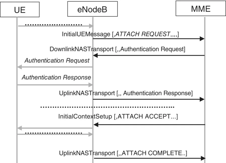
Figure 3.22 Illustration: LTE/EPS NAS transport between eNodeB and MME over S1 interface.
As illustrated in Figure 3.22, the LTE air interface initial NAS layer messages, e.g. ATTACH REQUEST, TAU, received from a UE is sent through the InitiaUEMessage from the eNodeB to the MME. The subsequent NAS messages between eNodeB and the MME are exchanged using the DownlinkNASTransport and UplinkNASTransport messages. The MME sends the ATTACH ACCEPT message to the eNodeB through the InitialContextSetup message. For more information on the NAS TRANSPORT messages and their contents, refer to TS 36.413 [97].
Between the RAN and the CN
Several similar procedures are performed between the RAN and its CN only over their respective logical interfaces, e.g. LTE/EPS S1 and X2; 5G NG; UMTS‐IuPS; and IuCS. Typical similar procedures are mentioned below:
Handover procedure performed in case of the GSM and LTE system; relocation procedure performed in case of UMTS system. A handover or relocation procedure is executed to transfer an ongoing call from one cell to another suitable cell.
Interface management – to setup, initialize, and release the respective interfaces, i.e. A, Gb, Iu, S1, and 5G system NG interface.
Security and encryption.
Paging – to notify an incoming call for an MS/UE.
UE tracking – to track a particular UE/MS.
Overload control from CN – which indicates the RAN to reduce the signaling load toward the CN.
Several functions are performed by a network element to complete a particular protocol layer procedure as highlighted above, which are described later in different chapters. For more information on the above functions and procedures, refer to TS 25.413 [54], TS 36.413 [97], TS 38.413 [119], and TS 48.008 [134].
3.12.2 Specific Functions and Procedures over the CN Interfaces
Some functions and procedures performed over a CN logical interface are specific to a GSM, UMTS, LTE, or 5G system. Typical examples of such GSM, UMTS, and LTE system‐specific functions over their specific logical interface are mentioned below:
BSSMAP [between GSM BSC – MSC]Speech transcoding from 64 kbps, at MSC end, to 16 kbps, at BSC end
RANAP [between UMTS/UTRAN RNC – MSC]UMTS Radio Access Bearer management, i.e. establish, modify, release, create, and allocate radio access bearer to the UETransport and RNL link management functions
S1‐AP [between LTE/E‐UTRAN eNodeB – MME]LTE/EPS Radio Access Bearer management, i.e. setup, modify, release, to create and allocate radio access bearer to the UETransport and RNL link management functions
NG‐AP [between 5G NG‐RAN – AMF]5G PDU Session Management, i.e. setup, modify, and release, a PDU session to a UE, MM, UE context management, and so onTransport and RNL link management functions.
For more information on the specific functions and procedures, refer to TS 25.413 [54], TS 36.413 [97], TS 48.008 [134], and TS 38.413 [119].
Chapter Summary
This chapter has introduced the core aspects of the understanding, design, and development of logical interfaces, their protocol stack, and its layers of mobile communications systems and networks. Logical interfaces are used to communicate among network elements of a mobile communications network. Logical interfaces are also used for the interworking and interoperations of mobile communications systems and networks, which shall be described later in Chapter 6.
Different terminologies are used to describe a logical interface, its protocol stack, and layers. Protocol layers are classified into user plane and control or signaling plane distinctly based on the nature of the information that is transmitted over a particular logical interface. Within the control plane only, protocol layers are also grouped into the AS and NAS categories, especially in the UMTS, LTE, and 5G networks and systems.
We presented the protocol layer termination and sublayering of a particular protocol layer found in mobile communications systems and networks. We also presented the general working model of a protocol layer that is used to communicate with its peer layer and provide services to an upper layer. Apart from this, we presented the general protocol model and layers of the UMTS UTRAN, LTE E‐UTRAN, and 5G NG‐RAN and their respective CNs.
Читать дальшеИнтервал:
Закладка:
Похожие книги на «Mobile Communications Systems Development»
Представляем Вашему вниманию похожие книги на «Mobile Communications Systems Development» списком для выбора. Мы отобрали схожую по названию и смыслу литературу в надежде предоставить читателям больше вариантов отыскать новые, интересные, ещё непрочитанные произведения.


Обсуждение, отзывы о книге «Mobile Communications Systems Development» и просто собственные мнения читателей. Оставьте ваши комментарии, напишите, что Вы думаете о произведении, его смысле или главных героях. Укажите что конкретно понравилось, а что нет, и почему Вы так считаете.