Andrea Vacca - Hydraulic Fluid Power
Здесь есть возможность читать онлайн «Andrea Vacca - Hydraulic Fluid Power» — ознакомительный отрывок электронной книги совершенно бесплатно, а после прочтения отрывка купить полную версию. В некоторых случаях можно слушать аудио, скачать через торрент в формате fb2 и присутствует краткое содержание. Жанр: unrecognised, на английском языке. Описание произведения, (предисловие) а так же отзывы посетителей доступны на портале библиотеки ЛибКат.

- Название:Hydraulic Fluid Power
- Автор:
- Жанр:
- Год:неизвестен
- ISBN:нет данных
- Рейтинг книги:3 / 5. Голосов: 1
-
Избранное:Добавить в избранное
- Отзывы:
-
Ваша оценка:
Hydraulic Fluid Power: краткое содержание, описание и аннотация
Предлагаем к чтению аннотацию, описание, краткое содержание или предисловие (зависит от того, что написал сам автор книги «Hydraulic Fluid Power»). Если вы не нашли необходимую информацию о книге — напишите в комментариях, мы постараемся отыскать её.
Readers of
will benefit from:
Approaching hydraulic fluid power concepts from an “outside-in” perspective, emphasizing a problem-solving orientation Abundant numerical examples and end-of-chapter problems designed to aid the reader in learning and retaining the material A balance between academic and practical content derived from the authors’ experience in both academia and industry Strong coverage of the fundamentals of hydraulic systems, including the equations and properties of hydraulic fluids
is perfect for undergraduate and graduate students of mechanical, agricultural, and aerospace engineering, as well as engineers designing hydraulic components, mobile machineries, or industrial systems.
Hydraulic Fluid Power — читать онлайн ознакомительный отрывок
Ниже представлен текст книги, разбитый по страницам. Система сохранения места последней прочитанной страницы, позволяет с удобством читать онлайн бесплатно книгу «Hydraulic Fluid Power», без необходимости каждый раз заново искать на чём Вы остановились. Поставьте закладку, и сможете в любой момент перейти на страницу, на которой закончили чтение.
Интервал:
Закладка:
3 1.3 Consider the hydraulic system below. It includes two fluid sources (generically represented) that supply two circuits: one circuit is to pilot the actuation of valve 1, and one circuit supplies the main flow through the hydraulic actuator, cylinder 2. What happens to the cylinder 2 when the valve 1 is pushed and held?It extends immediately and remains extended.It extends after a certain time interval, necessary to fill the accumulator.It remains in equilibrium, not moving at all.It retracts immediately, and it remains retracted.Retract immediately and extend after a certain time interval.Motivate your answer.
4 1.4 Consider again Problem 1.3, now with a modification of the hydraulic schematic as shown below. The pilot‐operated valve includes now a spring. Does the behavior of the hydraulic cylinder 2 change? Motivate your answer.
5 1.5 A hydraulic control system uses a 5 kW engine to drive a hydraulic motor (10 cm3/rev, gear type with external drain) and a single‐acting hydraulic cylinder (piston diameter: 80 mm, rod diameter: 40 mm). The single‐acting cylinder is used to lift and lower a gravitational load. The two actuators are independently supplied by two fixed displacement gear pumps (10 cm3/rev) both connected to the thermal engine. Both pumps are protected by system overpressurization through relief valves (pressure setting of 250 bar). Each pump is connected to the actuator through a directional valve that allows both directions of motion for the actuators. For controlling the hydraulic motor, a 4/3 valve is used. Instead, the single‐acting cylinder is actuated through a 3/3 directional control valve. The retraction of the cylinder occurs through gravity. For this purpose, between the 3/3 valve and the cylinder, there is a check valve in parallel with a fixed orifice, calibrated for achieve a flow of 10 l/min during the lowering condition. Both directional control valves are solenoid operated. In rest conditions, no flow is supplied to both actuators, even if no load holding is achieved.Represent the hydraulic schematic of the system, with particular attention to the positions of each directional control valve.
2 Hydraulic Fluids
This chapter provides a brief description of the properties of hydraulic fluids. In general, the working fluid can be considered as the main component of the hydraulic system. The fluid is the media that transports the energy between different parts of the system; it can change its energy level as it flows through hydraulic components. Beyond this main function, the working fluid also lubricates the internal parts of the hydraulic components. Another important function of the hydraulic fluid is heat removal: the working fluid carries the heat that is generated within certain components of the hydraulic system and can be cooled using proper heat exchangers (HEs).
A deep analysis of the working fluid properties requires a solid base of chemistry, also because nowadays fluids are often a mix of several components and additives, in appropriate quantities to achieve the desired properties. For example, some fluids are fire resistant, while others are designed to work in some hazardous environments. However, the description of the fluid as energy transfer media requires only a limited number of fluid parameters. This chapter introduces these parameters, and it allows the reader to understand some considerations made throughout the next chapters of the textbook. Additional bibliographic references are provided for the reader that is interested in further studying the topic of hydraulic fluids.
2.1 Ideal vs. Actual Hydraulic Fluids
As mentioned before, the hydraulic fluid can be seen as a “distributed” component of the system. This concept can be described with the help of Figure 2.1, which shows a very simple hydraulic circuit that moves a linear actuator (CYL). The circuit is composed by a pump (P) driven by an electric motor (EM). The pump displaces fluid from the tank (T) to a directional control valve (DCV), which determines the direction of the flow from the pump to the actuator. Depending on the DCV configuration, the actuator rod (CYL) can move to the right, to the left, or remain at rest. A relief valve (RV) is used to limit the maximum pressure at the pump outlet, protecting it from overpressurization. The circuit also has a filter (F) that ensures the proper cleanness level of fluid, removing the solid contaminants coming from component wear or entering the circuit through the cylinder lip seals. Finally, an HE removes excess heat from the fluid. The hydraulic lines connecting all the components mentioned above represent pipes or hoses used to connect the different parts of the circuit.
A more detailed description of each component will be provided in the following chapters of the book; the reader at this point should not worry too much about having a full understanding of the operation of the above circuit. In general, each component has a certain function in the system operation, and its functionality can be studied by considering either its ideal behavior or its actual behavior. The ideal behavior represents the best possible scenario, i.e. it excludes the presence of undesirable – yet unavoidable – phenomena such as leakages, frictions, etc. Instead, the actual behavior is representative of the real‐world operation, which accounts for the presence of these undesired effects. For example, the motion of the actuator (CYL) ideally occurs without frictional losses or leakages between the piston and the cylinder bore. In reality, these undesirable aspects are present during the operation of the system. Because of that, the energy required to generate the piston motion is higher than the energy that would be involved in the ideal case.
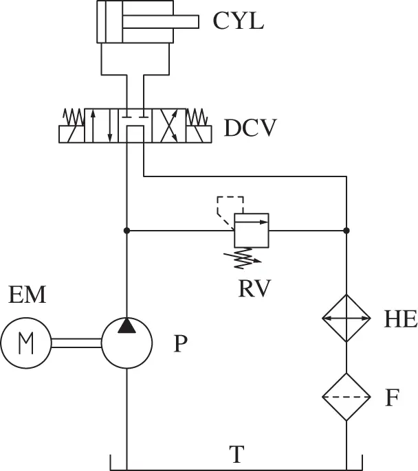
Figure 2.1 Example of simple hydraulic circuit. The hydraulic fluid can be imagined as an additional “distributed component” of the circuit.
In the analysis of engineering problems, the use of ideal models greatly simplifies the circuit analysis. The ideal case is also useful to define a reference behavior that can be used to quantify the relative performance of an actual system or component. Important parameters such as energy efficiency will also be defined in this book by comparing the ideal use of energy of a system (or a component) with respect to the actual behavior.
Imagining the working fluid as a physical component of a hydraulic system might not be an obvious assumption. However, from a very high level, the hydraulic fluid can be seen as a physical element present everywhere in the circuit. Similar to other components of the entire system, the hydraulic fluid accomplishes specific functions, and its behavior can be described by either an ideal or a realistic model. In particular, the hydraulic fluid is a distributed “imaginary” component that accomplishes the following functions:
Energy transport. With reference to Figure 2.1, the energy in the system flows from the prime mover (EM) through the pump (P) to the rest of the hydraulic system and finally to the end user (CYL). This transport occurs thanks to the fluid particles that travel and vary their energy level throughout the hydraulic system. This is the main function of the working fluid in a fluid power system. The lines dedicated to the transport of the energy are represented with continuous lines (see example in Figure 2.1).
Lubrication. Many hydraulic components have internal parts in relative motion. The hydraulic fluid can lubricate these parts, avoiding solid‐to‐solid contacts that can lead to wear and energy dissipation. On the other hand, the fluid should be selected to avoid excessive leakages through the clearances between the solid part.
Читать дальшеИнтервал:
Закладка:
Похожие книги на «Hydraulic Fluid Power»
Представляем Вашему вниманию похожие книги на «Hydraulic Fluid Power» списком для выбора. Мы отобрали схожую по названию и смыслу литературу в надежде предоставить читателям больше вариантов отыскать новые, интересные, ещё непрочитанные произведения.


Обсуждение, отзывы о книге «Hydraulic Fluid Power» и просто собственные мнения читателей. Оставьте ваши комментарии, напишите, что Вы думаете о произведении, его смысле или главных героях. Укажите что конкретно понравилось, а что нет, и почему Вы так считаете.