Andrea Vacca - Hydraulic Fluid Power
Здесь есть возможность читать онлайн «Andrea Vacca - Hydraulic Fluid Power» — ознакомительный отрывок электронной книги совершенно бесплатно, а после прочтения отрывка купить полную версию. В некоторых случаях можно слушать аудио, скачать через торрент в формате fb2 и присутствует краткое содержание. Жанр: unrecognised, на английском языке. Описание произведения, (предисловие) а так же отзывы посетителей доступны на портале библиотеки ЛибКат.

- Название:Hydraulic Fluid Power
- Автор:
- Жанр:
- Год:неизвестен
- ISBN:нет данных
- Рейтинг книги:3 / 5. Голосов: 1
-
Избранное:Добавить в избранное
- Отзывы:
-
Ваша оценка:
Hydraulic Fluid Power: краткое содержание, описание и аннотация
Предлагаем к чтению аннотацию, описание, краткое содержание или предисловие (зависит от того, что написал сам автор книги «Hydraulic Fluid Power»). Если вы не нашли необходимую информацию о книге — напишите в комментариях, мы постараемся отыскать её.
Readers of
will benefit from:
Approaching hydraulic fluid power concepts from an “outside-in” perspective, emphasizing a problem-solving orientation Abundant numerical examples and end-of-chapter problems designed to aid the reader in learning and retaining the material A balance between academic and practical content derived from the authors’ experience in both academia and industry Strong coverage of the fundamentals of hydraulic systems, including the equations and properties of hydraulic fluids
is perfect for undergraduate and graduate students of mechanical, agricultural, and aerospace engineering, as well as engineers designing hydraulic components, mobile machineries, or industrial systems.
Hydraulic Fluid Power — читать онлайн ознакомительный отрывок
Ниже представлен текст книги, разбитый по страницам. Система сохранения места последней прочитанной страницы, позволяет с удобством читать онлайн бесплатно книгу «Hydraulic Fluid Power», без необходимости каждый раз заново искать на чём Вы остановились. Поставьте закладку, и сможете в любой момент перейти на страницу, на которой закончили чтение.
Интервал:
Закладка:
Finally, Figure 1.11presents some symbols used for accessory elements and sensors. Accessories can be accumulators, coolers, filters, and breathers. These symbols can be simple or more articulated if it is necessary to identify additional features such as for the case of a filter with bypass valve and differential pressure switch. It is again a matter of the level of details that the designer wants to highlight in the circuit.
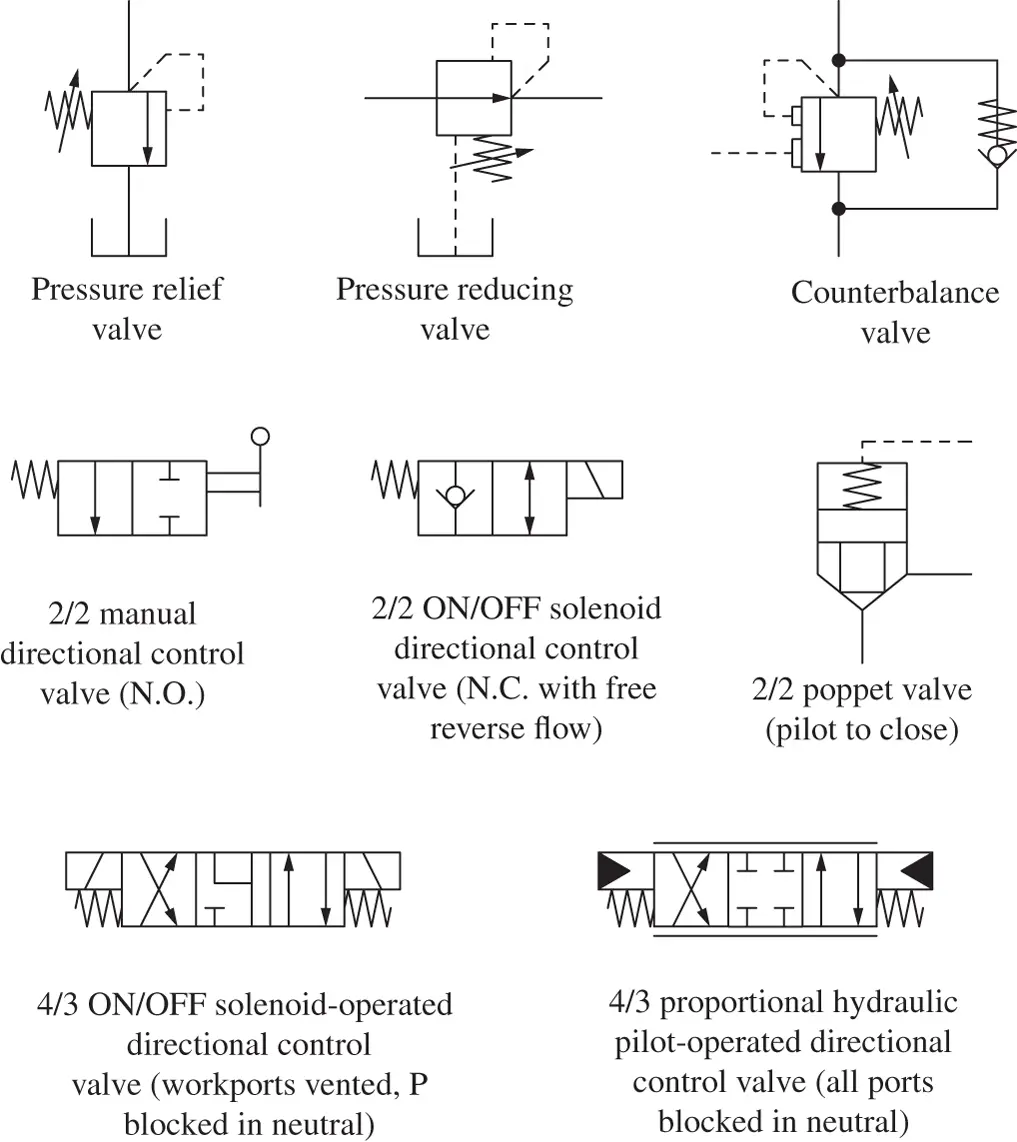
Figure 1.10 Common symbols utilized for directional and pressure control elements.
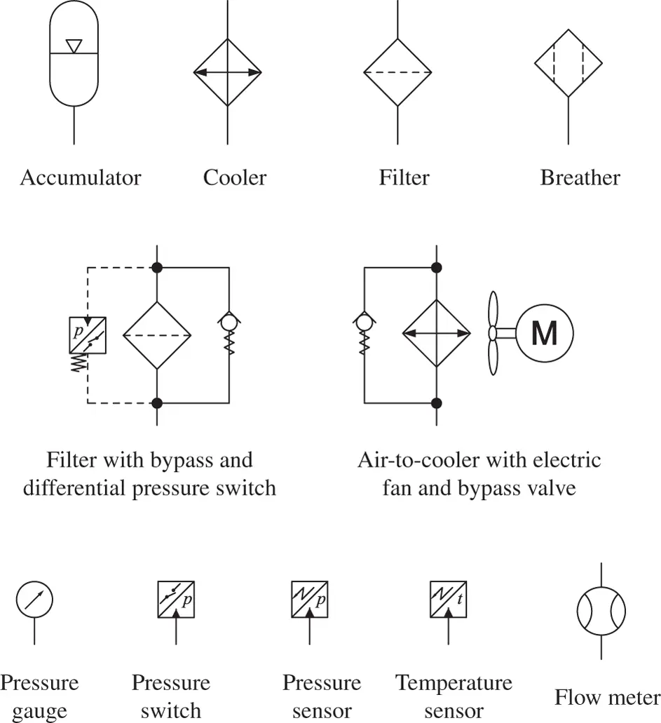
Figure 1.11 Symbols used for accessory elements and sensors.
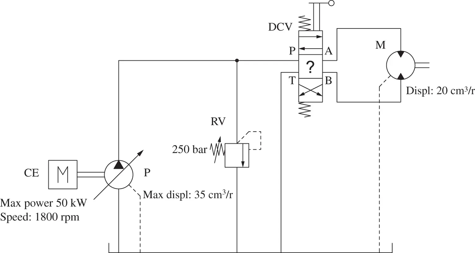
Example 1.1 Hydraulic schematic for a conveyor application
A hydraulic system is used to control a bidirectional conveyor. The system uses a 50 kW internal combustion engine (shaft speed of 1800 rpm ) to drive a 35 cm 3/ rev variable displacement axial piston pump. The conveyor is driven by a 20 cm 3/ rev fixed displacement hydraulic motor (a bidirectional gear motor with a drain, rated speed of 1800 rpm ). The control of the direction of rotation of the motor is achieved by means of 4/3 directional control valve, manually operated. The motor does not rotate in rest condition. The maximum system pressure has to be limited to 200 bar , and for this purpose one or more pressure relief valves can be used.
Draw the schematic of the circuit according to the basic rules of the ISO 1219 standard of representation, and comment on the operation of the system in standby conditions.
Given:
The generic description of a hydraulic system, which includes:
a prime mover (internal combustion engine), with power and shaft speed of n = 1800 rpm;
a variable displacement hydraulic pump (axial piston type) driven by the abovementioned engine, Vp = 35 cm3/rev;
a 4/3 directional control valve (details of the position not given), manually operated;
a hydraulic bidirectional motor, Vm = 20 cm3/rev, connected to the above valve; and
one or more relief valves (pressure setting p* = 250 bar), which accomplish the safety function (preventing excessive system pressurization).
Find:
The hydraulic schematic according to the ISO standard of representation.
Solution:
A possible representation of the hydraulic system is given by the figures below.
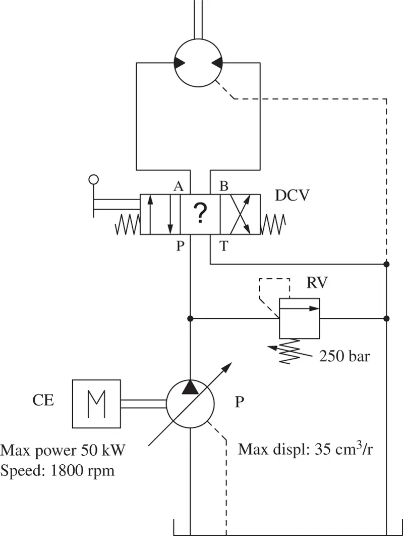
Alternative representation:
Remarks:
The schematic in the top figure follows a left‐to‐right direction of representation. Starting from the prime mover positioned to the left, the schematic ends with the hydraulic function, or the actuator, at the right side of the schematic. As an alternative, the representation from bottom (prime mover) to top (actuator) is provided in the bottom figure.
Either of these two options for representing a hydraulic system is acceptable, and it usually increases the readability and facilitates a quick understanding of the functioning of the system.
The schematic must represent the operation of the system during rest condition. In other words, the connections of the supply pump and those of the actuator must be aligned to the central (or neutral position) of the directional control valve (DCV). These connections are indicated with the letters P (connection to the supply pump), T (connection to tank), A, and B (actuator workports). This central (or neutral position) corresponds to the configuration of the system when the DCV is not actuated. In position 1 (parallel arrow), the hydraulic motor rotates in one direction (i.e. clockwise). In position 2 (crossed arrows), the hydraulic motor rotates in the opposite direction (i.e. counterclockwise).
Most of the component details defined in the problem statement are useful information for the analysis of the system, and therefore they are reported in the schematic as suggested by ISO 1219. The construction type of the pump (axial piston pump) and of the motor (gear motor) is not provided because it is not essential for a basic study of the system. This additional information, such as the component manufacturer and the component code, and other information, can be reported in a separated table.
The size of the component is not reflected in the size used for the corresponding symbol. For the case of this problem, the size of the circle used to represent the pump is the same of the one used to represent the hydraulic motor, even if the pump has a larger displacement.
One pressure relief valve is used to protect the system against overpressurization. This relief valve is placed at the pump outlet, thus preventing the pump to supply fluid at a pressure higher than p*. A sophisticated control of the pump displacement might integrate this feature (this will be seen in Part 3). However, since it is unknown if the pump has a pressure limiting device integrated into its design, a relief valve is included in the figure above.
The problem statement does not specify the neutral position of the DCV, although it specifies that in neutral the fan speed should be null.
As it will be seen later ( Chapter 8), DCV can easily implement different options for the rest position. For this problem, the designer could choose among the options below.
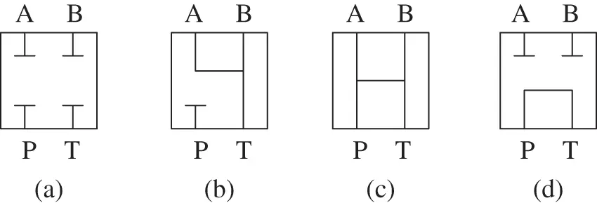
In the hydraulic schematic shown above, the selected neutral position is (c). In this position all ports P, T, A, B are connected to tank. This allows the pump to divert the flow to the tank (which is the path of minimum effort for the fluid), thus maintaining the outlet port P at a minimum pressure. The motor ports are also connected to tank; therefore the fan will not rotate since no flow energy is provided to the hydraulic motor. Position (b) would be another reasonable solution, although it would require a pump able to adjust its instantaneous displacement to zero in rest conditions. Otherwise, in rest conditions, the pump would supply flow to the relief valve RV, thus at the maximum allowable pressure, requesting high energy to the CE. Position (a) and (d) would block the motor ports; this would cause excessive pressure at the motor workports when the fan is brought to a sudden stop through the DCV. Such positions would require additional relief valves to handle these transients.
Problems
1 1.1 Using following symbols, represent a schematic of a hydraulic system that rotates the hydraulic motor in both directions. All the circuit branches need to be protected from overpressure using proper pressure relief valve(s). Symbols with (*) can have more instances. Use the minimum number of components.Does the system have an “on/off” regulation nature, or does it implement a variable angular speed of the load?
2 1.2 Solve again Problem 1.1. But instead of using the manually operated valve, use the electrically operated directional valve shown below.
Читать дальшеИнтервал:
Закладка:
Похожие книги на «Hydraulic Fluid Power»
Представляем Вашему вниманию похожие книги на «Hydraulic Fluid Power» списком для выбора. Мы отобрали схожую по названию и смыслу литературу в надежде предоставить читателям больше вариантов отыскать новые, интересные, ещё непрочитанные произведения.


Обсуждение, отзывы о книге «Hydraulic Fluid Power» и просто собственные мнения читателей. Оставьте ваши комментарии, напишите, что Вы думаете о произведении, его смысле или главных героях. Укажите что конкретно понравилось, а что нет, и почему Вы так считаете.