Andrea Vacca - Hydraulic Fluid Power
Здесь есть возможность читать онлайн «Andrea Vacca - Hydraulic Fluid Power» — ознакомительный отрывок электронной книги совершенно бесплатно, а после прочтения отрывка купить полную версию. В некоторых случаях можно слушать аудио, скачать через торрент в формате fb2 и присутствует краткое содержание. Жанр: unrecognised, на английском языке. Описание произведения, (предисловие) а так же отзывы посетителей доступны на портале библиотеки ЛибКат.

- Название:Hydraulic Fluid Power
- Автор:
- Жанр:
- Год:неизвестен
- ISBN:нет данных
- Рейтинг книги:3 / 5. Голосов: 1
-
Избранное:Добавить в избранное
- Отзывы:
-
Ваша оценка:
Hydraulic Fluid Power: краткое содержание, описание и аннотация
Предлагаем к чтению аннотацию, описание, краткое содержание или предисловие (зависит от того, что написал сам автор книги «Hydraulic Fluid Power»). Если вы не нашли необходимую информацию о книге — напишите в комментариях, мы постараемся отыскать её.
Readers of
will benefit from:
Approaching hydraulic fluid power concepts from an “outside-in” perspective, emphasizing a problem-solving orientation Abundant numerical examples and end-of-chapter problems designed to aid the reader in learning and retaining the material A balance between academic and practical content derived from the authors’ experience in both academia and industry Strong coverage of the fundamentals of hydraulic systems, including the equations and properties of hydraulic fluids
is perfect for undergraduate and graduate students of mechanical, agricultural, and aerospace engineering, as well as engineers designing hydraulic components, mobile machineries, or industrial systems.
Hydraulic Fluid Power — читать онлайн ознакомительный отрывок
Ниже представлен текст книги, разбитый по страницам. Система сохранения места последней прочитанной страницы, позволяет с удобством читать онлайн бесплатно книгу «Hydraulic Fluid Power», без необходимости каждый раз заново искать на чём Вы остановились. Поставьте закладку, и сможете в любой момент перейти на страницу, на которой закончили чтение.
Интервал:
Закладка:
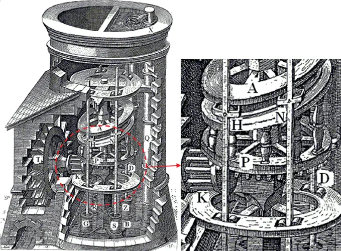
Figure 1.1 The axial piston pump sketched by A. Ramelli [1].
In the United States, Arthur Parker (1885–1945) founded the Parker Appliance Company in 1918 ( Figure 1.3). The firm started with producing pneumatic components for air compressors and moved into brake systems for vehicles. The success of the company strengthened in the 1930s shifting into the production of fittings for the aircraft industry. Today Parker Hannifin Corp. is a large group providing hydraulic, fluid connector, and motion control solutions for mobile, industrial, and aerospace businesses.
In the same century several individuals fueled the industrialization of hydraulics in Europe. For example, in Germany, Alfred Rexroth (1899–1978) led the company founded by his ancestor Georg Ludwig Rexroth in 1975 into the development of hydraulic components. Initially, in the 1950s, industrial production involved casted valves and gear pumps. In the first half of 1960s, industrial manifolds and mobile directional control spool valves were introduced. The second part of the decade instead saw the evolution of radial and axial piston pumps. In the 1970s hydraulics started merging with electronics; the first servo valves for industrial applications were introduced to the market. Also in Germany, Carl Von Linde founded with two other partners in 1904, the company known today as Linde Group. The company started specializing in refrigeration systems and introduced to the market hydrostatic‐propelled vehicles in 1956. Linde Hydraulics launched the first load sensing (LS) valve in 1986. The industrialization of fluid power was not limited to Germany, but saw many historic contributions also in England, Italy, Sweden, and Eastern Europe.
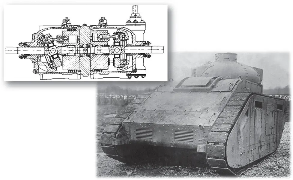
Figure 1.2 The Williams–Janney transmission was based on axial piston design units and used to propel one of the first infantry tanks (1905).
Fluid power technology, including oil hydraulic and pneumatic systems, is recognized in academia as an independent discipline that has defined research and scholarly activities since the Second World War. In particular, the Massachusetts Institute of Technology (MIT) in the United States started working on the development of hydraulic control systems since 1939. An initially small team rapidly grew larger, making contributions in hydraulic components design and hydraulic control theories and calculation methods that are still considered fundament of fluid power discipline. Published in 1959, the work by MIT faculty Blackburn, Reethof, and Shearer [2] is perhaps the greatest technical manuscript ever written on fluid power technology, and it has influenced many following books, including this one.
Many other universities followed MIT and established research institutes expressly devoted to fluid power research. Many of these departments are still alive, shaping research on fluid power technology. A list of the most of these research centers can be found in [3].
The authors encourage the reader interested in learning more about the main historical passages of the hydraulic fluid power technology to consult Skinner's book [4].
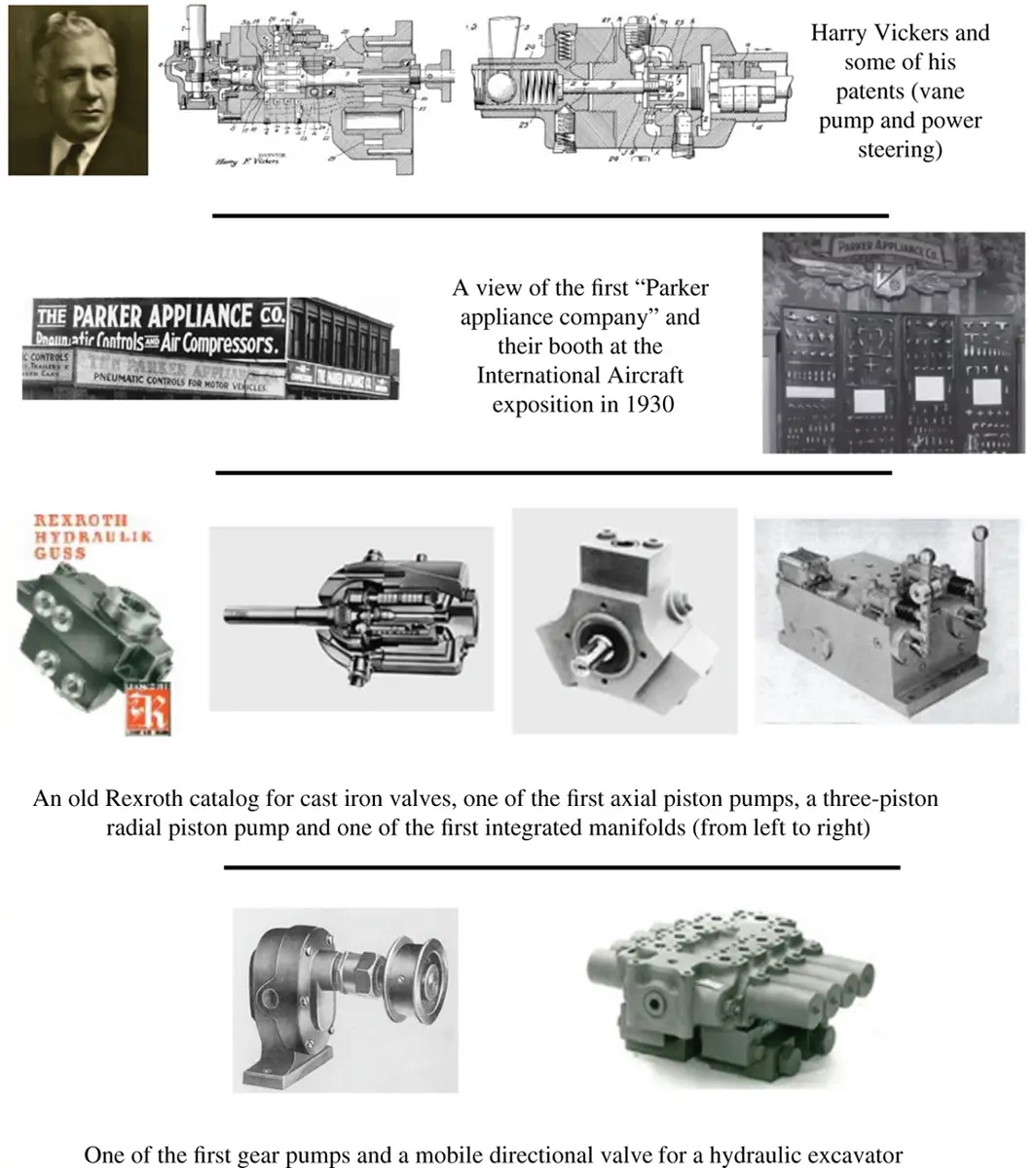
Figure 1.3 A collage of pictures from historical moments of the fluid power industry.
Sources: Various online sources.
1.2 Fluid Power Symbology and Its Evolution
One of the main barriers in the past for exchanging technical information related to hydraulics has been the lack of a common “language”: a standard way to represent hydraulic circuits and systems. Figures 1.4and 1.5show two examples of hydraulic circuits represented in some “old fashion” styles. Even if the circuits are fairly simple, their representation is not of immediate understanding. They have different ways of indicating the components along with their functions in the circuit; one circuit shows component cutaways, while the other one describes the function of every part with arrowheads and text. Also, one circuit tries to give a detailed representation of the system layout and piping, while the other one uses straight lines between the ports.
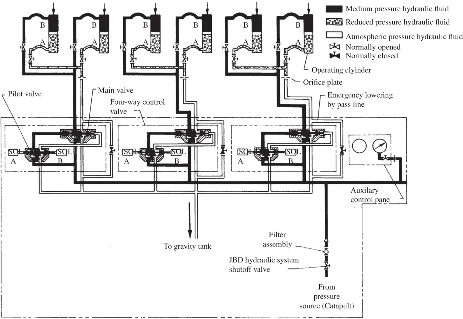
Figure 1.4 Hydraulic system of a jet blast deflector.
Source: Beasley 1990.
A multitude of different approaches for representing hydraulic circuits were developed in the past by various companies and fluid power institutes. The aim was the same: representing on a single sheet of paper the system functions, the layout, and the design details of the components. However, the result was different. This lack of commonality represented an obstacle to the development of a common science.
The discussion on fluid power symbols and standards was initiated in the United States by the Joint Industry Conference (JIC) in 1944, and the first JIC‐defined hydraulic symbols and standards were released in 1948. Soon after, the national standardization organizations took over: in 1958 the American Standards Association (ASA) released their revised version of the JIC standard. In Europe, the Comité Européen des Transmissions Oleohydrauliques et Pneumatiques (CETOP), founded in 1962, provided a series of recommendations on graphic symbols for fluid power that were received and approved by the International Organization for Standardization (ISO).
Finally, in 1976, the first version of ISO 1219 standard Fluid Power Systems and Components: Graphic Symbols and Circuit Diagrams was released. The ISO 1219 ( parts 1and 2) is frequently revised and updated. It is nowadays considered as the universal reference for representing hydraulic circuits.
ISO 1219 standard is the universal reference for representing hydraulic circuits. In engineering problems involving a hydraulic control system, it is always recommended to represent the system schematic using ISO symbols and following the criteria suggested by the standard.
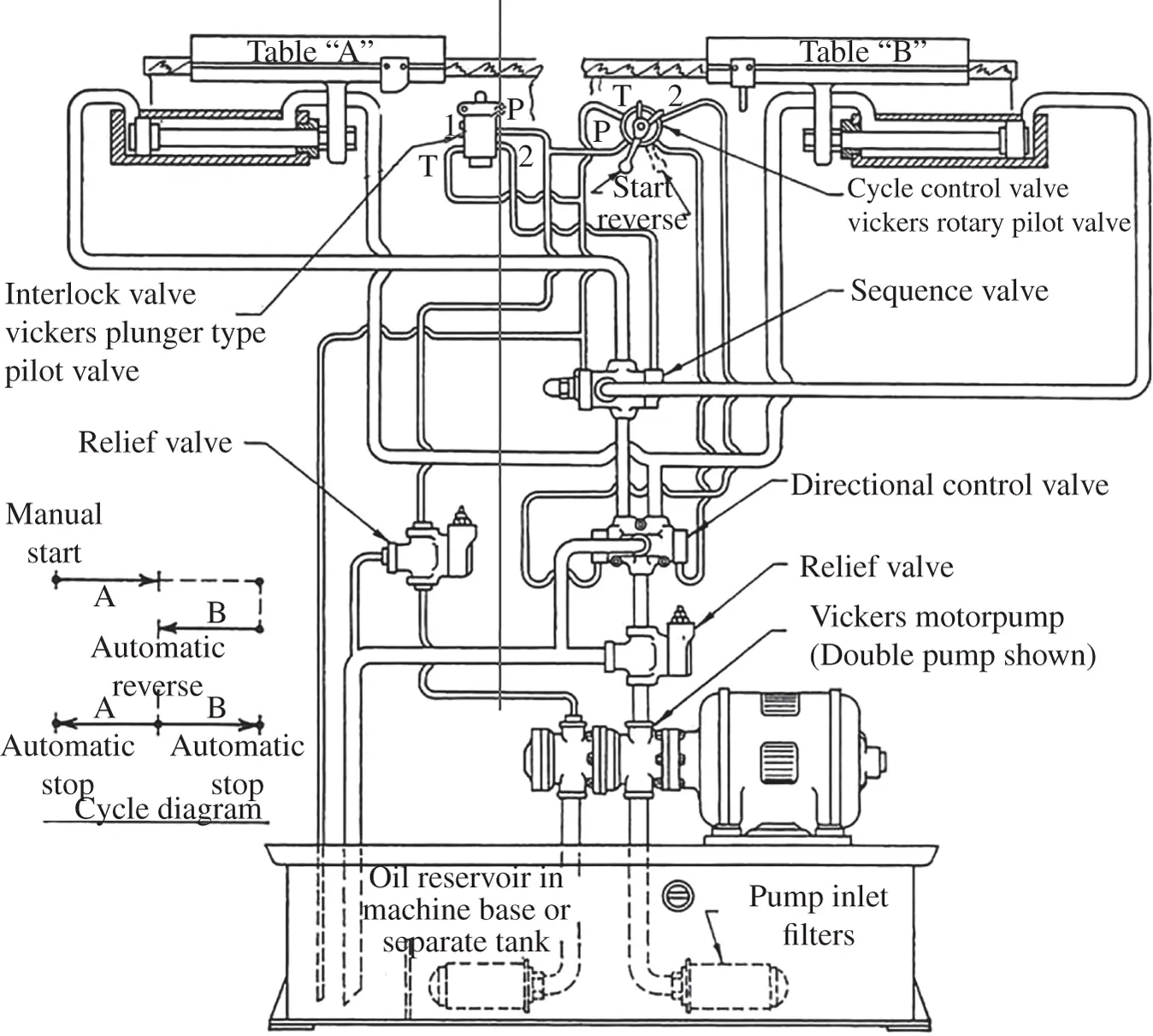
Figure 1.5 Hydraulic circuit with pilot‐controlled sequence valve.
Source: Harry Franklin Vickers, 1989.
The detailed description of the ISO 1219 standard is beyond the scope of this book; all rules and conventions can be found on these two ISO standards [5, 6]. However, it is still worthwhile to summarize the primary and most important aspects introduced by the standard:
Function representation. The hydraulic circuit schematic should focus only on the functionality of both the components and system, whereas other information such as mechanical details of the parts or physical layout of the system should not be represented.
Symbols. The standard includes precise recommendations about the symbol to be utilized to represent a specific component. The symbol itself contains relevant information necessary to understand the functionality of the component.
Additional information. In the schematic of the system, each symbol needs to comprise information necessary to understand the operation. These include a label that uniquely identifies the component, particular function of the component, and sizing information.
Читать дальшеИнтервал:
Закладка:
Похожие книги на «Hydraulic Fluid Power»
Представляем Вашему вниманию похожие книги на «Hydraulic Fluid Power» списком для выбора. Мы отобрали схожую по названию и смыслу литературу в надежде предоставить читателям больше вариантов отыскать новые, интересные, ещё непрочитанные произведения.


Обсуждение, отзывы о книге «Hydraulic Fluid Power» и просто собственные мнения читателей. Оставьте ваши комментарии, напишите, что Вы думаете о произведении, его смысле или главных героях. Укажите что конкретно понравилось, а что нет, и почему Вы так считаете.