Andrea Vacca - Hydraulic Fluid Power
Здесь есть возможность читать онлайн «Andrea Vacca - Hydraulic Fluid Power» — ознакомительный отрывок электронной книги совершенно бесплатно, а после прочтения отрывка купить полную версию. В некоторых случаях можно слушать аудио, скачать через торрент в формате fb2 и присутствует краткое содержание. Жанр: unrecognised, на английском языке. Описание произведения, (предисловие) а так же отзывы посетителей доступны на портале библиотеки ЛибКат.

- Название:Hydraulic Fluid Power
- Автор:
- Жанр:
- Год:неизвестен
- ISBN:нет данных
- Рейтинг книги:3 / 5. Голосов: 1
-
Избранное:Добавить в избранное
- Отзывы:
-
Ваша оценка:
Hydraulic Fluid Power: краткое содержание, описание и аннотация
Предлагаем к чтению аннотацию, описание, краткое содержание или предисловие (зависит от того, что написал сам автор книги «Hydraulic Fluid Power»). Если вы не нашли необходимую информацию о книге — напишите в комментариях, мы постараемся отыскать её.
Readers of
will benefit from:
Approaching hydraulic fluid power concepts from an “outside-in” perspective, emphasizing a problem-solving orientation Abundant numerical examples and end-of-chapter problems designed to aid the reader in learning and retaining the material A balance between academic and practical content derived from the authors’ experience in both academia and industry Strong coverage of the fundamentals of hydraulic systems, including the equations and properties of hydraulic fluids
is perfect for undergraduate and graduate students of mechanical, agricultural, and aerospace engineering, as well as engineers designing hydraulic components, mobile machineries, or industrial systems.
Hydraulic Fluid Power — читать онлайн ознакомительный отрывок
Ниже представлен текст книги, разбитый по страницам. Система сохранения места последней прочитанной страницы, позволяет с удобством читать онлайн бесплатно книгу «Hydraulic Fluid Power», без необходимости каждый раз заново искать на чём Вы остановились. Поставьте закладку, и сможете в любой момент перейти на страницу, на которой закончили чтение.
Интервал:
Закладка:
All the systems presented in this book will adhere to the ISO standard of representation. The additional information will be often omitted for the sake of generality. However, it is important to point out how this information should never be neglected when the circuit is designed for an actual application.
These three aspects of the ISO standard can be described with the example of Figure 1.6, which represents a basic system to control a hydraulic cylinder. The components are laid out in a way that is very intuitive: the oil flows from tank to the actuator following a bottom‐to‐top path; vice versa, the return oil flows from top to bottom. This is the most popular way of representing circuits: all the actuators are clearly located at the top, the power source elements at the bottom, and the control elements in the middle. An alternative layout can also follow a left‐to‐right path. Obviously, this is not related to the actual layout of the system.
The circuit comprises a hydraulic reservoir 1that supplies flow to a fixed displacement pump 3driven by an electric motor 2. The pump outlet is connected to a four‐way 3‐position (4/3) solenoid‐operated on/off directional control valve 5, which in neutral position connects P to T, while the workports A and B are blocked. The pump outlet is also connected to an adjustable pressure relief valve 4, which outlet is connected to the return line from 5to tank. The workports A and B of valve 5are supplying the linear actuator 6: in particular A is connected to the bore and B to the rod side. When solenoid Y1is energized, the valve shifts in the “parallel arrows” position, and the pump outlet is connected to the cylinder bore, while the cylinder rod is connected to tank. In this situation, the cylinder extends. When solenoid Y2is energized, valve 5shifts in the “crossed arrows” position, and the pump outlet flow is connected to the cylinder rod, while the bore discharges to tank; thus, the cylinder is retracted.
The circuit also provides the additional information needed to complete the understanding of the system operation. These include the size of the tank and the type of hydraulic fluid, the installed power of the electric motor, the shaft speed of the pump and the flow rate in the system, the maximum pressure in the system, the function of the valve solenoids, and reference to the electric connections. Even the size and length of the hydraulic lines are reported.
All essential features of the system operation should be derived from this information. For example, during cylinder extension, the velocity of the actuator is 0.24 m/s and the return flow 9.2 l/min, while during retraction these values are 0.47 m/s and 35.3 l/min. Similarly, the maximum power request can be estimated in 4 kW for the maximum allowed load at the cylinder.
The above description of the simple system of Figure 1.6emphasizes the large amount of information provided by a schematic that complies with the ISO standard. Many designers often miss the advantages offered by a correct representation of a circuit, which is extremely helpful at various design and maintenance phases of a hydraulic‐powered machine.
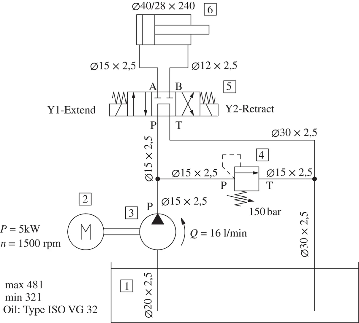
Figure 1.6 Hydraulic circuit for moving an actuator.
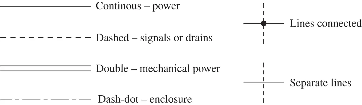
Figure 1.7 Meaning of different types of lines in hydraulic circuits.
1.3 Common ISO Symbols
The most common elements in hydraulic circuits are the hydraulic lines. As summarized in Figure 1.7, four line styles can be found in a schematic, and each one has a different meaning:
1 Continuous lines represent working power lines; for example, these are the lines connected to the outlet and inlet of pumps and motors.
2 Dashed lines represent pilot signals (for example, a load‐sensing line between a LS pump and a valve) or drain lines (for example, the case drain of a variable displacement unit).
3 Double lines represent mechanical power transmission, like in the case of a motor shaft.
4 Dash‐dot lines are instead used to indicate the physical layout of the system. When multiple components are enclosed in a dash‐dot line, they are part of the same physical unit as, for example, a hydraulic manifold.
Another important rule is that the intersection of two or more lines needs to be represented by a dot. If two lines intersect on paper without a dot, it means that they remain physically separated.
Figure 1.8represents the symbols for the most common prime movers (electric and motor and combustion engine) and for some elements that are often placed between the prime mover and the hydraulic energy conversion units. These can be gearboxes, clutches, or power takeoff s (PTOs) and can be equipped with different functionalities.
Figure 1.9presents common symbols for energy conversion units. Rotary units are represented with circles, while linear actuators use rectangles. The reader can notice that each symbol emphasizes different characteristics. For example, the symbol of the fixed displacement pump is the only one highlighting the pump rotation. The first variable displacement pump does not mention anything about the type of control, while the second one emphasizes that the pump displacement is regulated based on the value of the outlet pressure. As it will be presented in Part 2, the representation of the pump control can also be much more detailed. Depending on the case, the engineer can select the level of detail that needs to be presented in the hydraulic schematic.
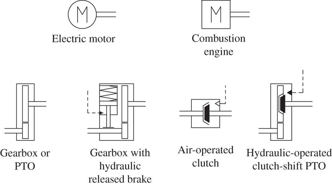
Figure 1.8 Common symbols for prime movers and mechanical rotary transmission elements.
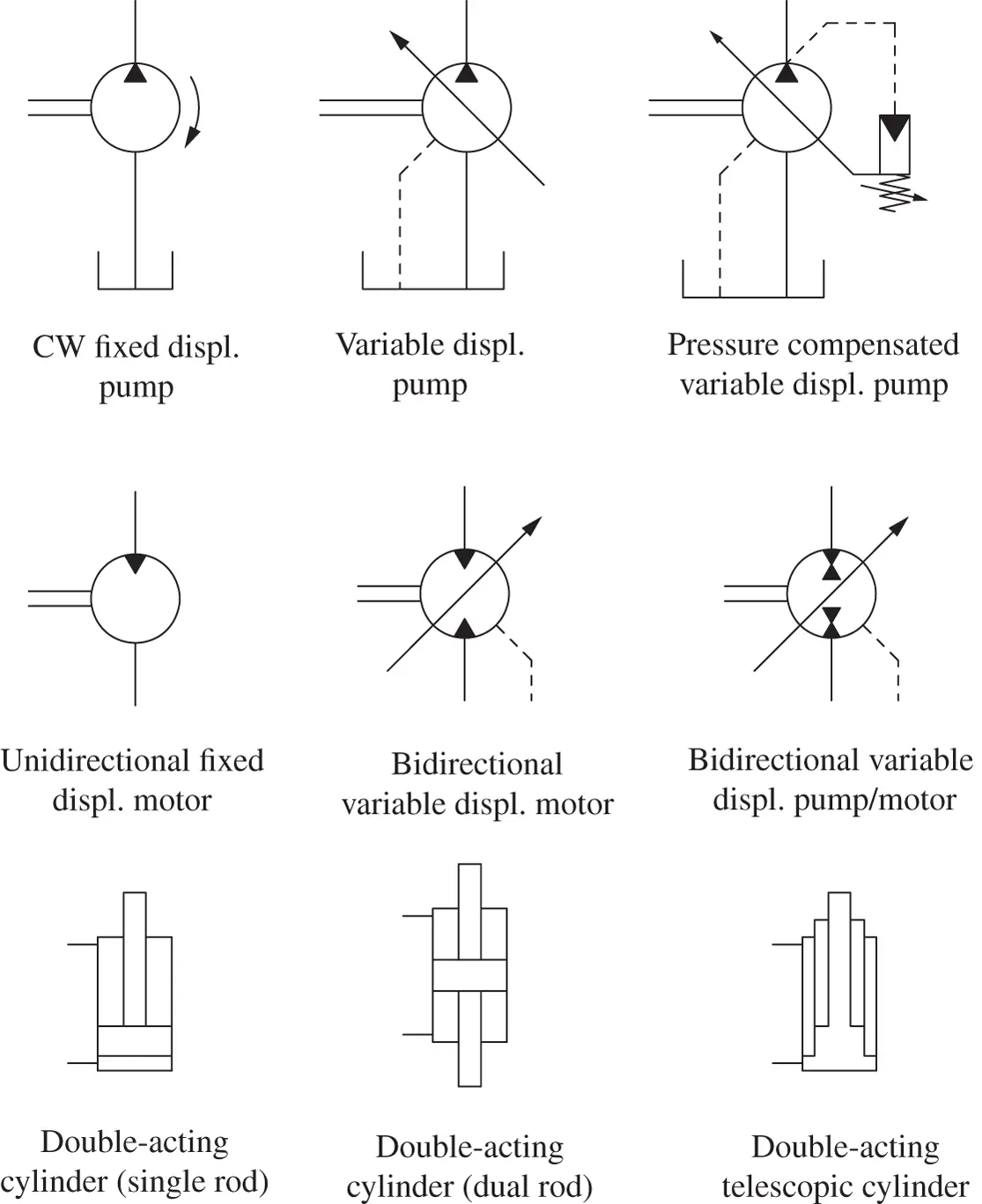
Figure 1.9 Common symbols utilized for prime movers and energy conversion units.
Figure 1.10reports some common symbols for pressure and directional control elements. These are always represented by squares that include arrows connecting the different ports. Each square represents the possible configurations of the valve. At the end of the squares, the actuation method is represented. This can be a solenoid, a spring, or an external or internal pilot pressure.
The elements on the first row of Figure 1.10are three very common pressure control devices: relief, reducing, and counterbalance valves. Relief valves are used to protect circuits from overpressurization and always discharge flow to tank. Reducing valves instead are used to reduce the supply pressure to a lower level. They are normally open valves where the spring is always drained to tank. Counterbalance valves are pressure control valves with two areas of influence that also include a check valve function. On the second row, three examples of two‐way two‐position valves are represented. Each valve has a different configuration and different control and implements a different application. The last row includes two examples of four‐way three‐position valves. The three squares indicate the neutral and the extreme positions. The first valve is a solenoid on/off valve, while the second one is a pilot‐operated proportional valve. More details about the characteristic of these elements will be provided in the following chapters.
Читать дальшеИнтервал:
Закладка:
Похожие книги на «Hydraulic Fluid Power»
Представляем Вашему вниманию похожие книги на «Hydraulic Fluid Power» списком для выбора. Мы отобрали схожую по названию и смыслу литературу в надежде предоставить читателям больше вариантов отыскать новые, интересные, ещё непрочитанные произведения.


Обсуждение, отзывы о книге «Hydraulic Fluid Power» и просто собственные мнения читателей. Оставьте ваши комментарии, напишите, что Вы думаете о произведении, его смысле или главных героях. Укажите что конкретно понравилось, а что нет, и почему Вы так считаете.