Ibrahim Dincer - Thermal Energy Storage Systems and Applications
Здесь есть возможность читать онлайн «Ibrahim Dincer - Thermal Energy Storage Systems and Applications» — ознакомительный отрывок электронной книги совершенно бесплатно, а после прочтения отрывка купить полную версию. В некоторых случаях можно слушать аудио, скачать через торрент в формате fb2 и присутствует краткое содержание. Жанр: unrecognised, на английском языке. Описание произведения, (предисловие) а так же отзывы посетителей доступны на портале библиотеки ЛибКат.
- Название:Thermal Energy Storage Systems and Applications
- Автор:
- Жанр:
- Год:неизвестен
- ISBN:нет данных
- Рейтинг книги:4 / 5. Голосов: 1
-
Избранное:Добавить в избранное
- Отзывы:
-
Ваша оценка:
Thermal Energy Storage Systems and Applications: краткое содержание, описание и аннотация
Предлагаем к чтению аннотацию, описание, краткое содержание или предисловие (зависит от того, что написал сам автор книги «Thermal Energy Storage Systems and Applications»). Если вы не нашли необходимую информацию о книге — напишите в комментариях, мы постараемся отыскать её.
Provides students and engineers with up-to-date information on methods, models, and approaches in thermal energy storage systems and their applications in thermal management and elsewhere Thermal Energy Storage: Systems and Applications
Thermal Energy Storage: Systems and Applications, Third Edition
Thermal Energy Storage Systems and Applications — читать онлайн ознакомительный отрывок
Ниже представлен текст книги, разбитый по страницам. Система сохранения места последней прочитанной страницы, позволяет с удобством читать онлайн бесплатно книгу «Thermal Energy Storage Systems and Applications», без необходимости каждый раз заново искать на чём Вы остановились. Поставьте закладку, и сможете в любой момент перейти на страницу, на которой закончили чтение.
Интервал:
Закладка:

Figure 1.17 A composite wall with many layers in series.
where, ∑ R t= R t,t= 1/ HA . Therefore, the overall heat transfer coefficient becomes
(1.106) 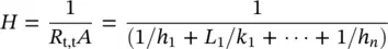
1.6.6 The Cylinder
A practical common object is a hollow cylinder, and a commonly encountered problem is the case of heat transfer through a pipe or cylinder. Consider that we have a cylinder of internal radius r 1and external radius r 2, whose inner and outer surfaces are in contact with fluids at different temperatures ( Figure 1.18). In a steady‐state form with no heat generation, the governing heat conduction equation is written as
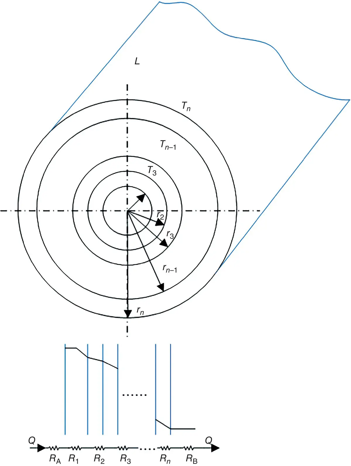
Figure 1.18 A hollow cylinder.
(1.107) 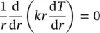
Based on Fourier's law, the rate at which heat is transferred by conduction across the cylindrical surface in the solid is expressed as
(1.108) 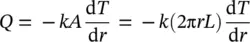
where A = 2𝜋 rL is the area normal to the direction of heat transfer.
To determine the temperature distribution in the cylinder, it is necessary to solve Eq. (1.107)under appropriate boundary conditions, by assuming that k is constant. By integrating Eq. (1.107)twice, the following heat transfer equation is obtained:
(1.109) 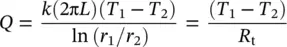
If we now consider a composite hollow cylinder, the heat transfer equation is found to be as follows, where interfacial contact resistances are neglected:
(1.110) 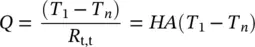
where R t,t= (1/2π r 1 Lh 1) + (ln( r 2/ r 1)/2π k 1 L ) + (ln( r 3/ r 2)/2π k 2 L ) + ⋯(1/2π r n Lh n)
1.6.7 The Sphere
The case of heat transfer through a sphere is not as common as the cylinder problem. Consider a hollow sphere of internal radius r 1and external radius r 2( Figure 1.19). Also, consider the inside and outside temperatures to be T 1and T 2, respectively, and constant thermal conductivity with no heat generation. We can express the heat conduction across the sphere wall in the form of Fourier's law:
(1.111) 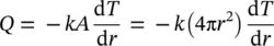
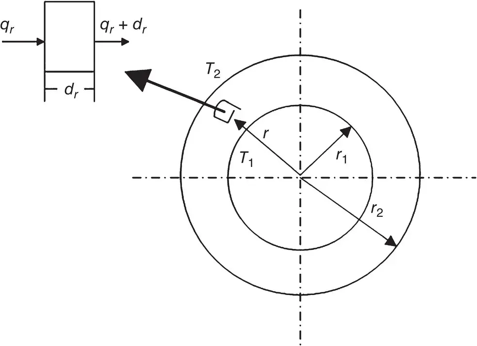
Figure 1.19 Heat conduction in a hollow sphere.
where, A = 4π r 2is the area normal to the direction of heat transfer.
After integrating Eq. (1.111), we obtain the following expression:
(1.112) 
If we now consider a composite hollow sphere, the heat transfer equation is determined to be as follows, neglecting interfacial contact resistances:
(1.113) 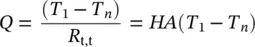
where, 
1.6.8 Conduction with Heat Generation
(a) The Plane Wall
Consider a plane wall, as shown in Figure 1.20a, in which there is uniform heat generation per unit volume. The heat conduction equation becomes
(1.114) 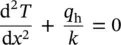
By integrating Eq. (1.114)with the prescribed boundary conditions, T (− L ) = T 1and T ( L ) = T 2. The temperature distribution can be obtained as
(1.115) 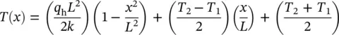
The heat flux at any point in the wall can be found, depending on x , by using Eq. (1.115)with Fourier's law.
If T 1= T 2≡ T s, the temperature distribution is symmetrical about the midplane ( Figure 1.20b). Then,
(1.116) 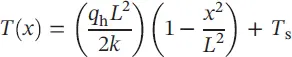
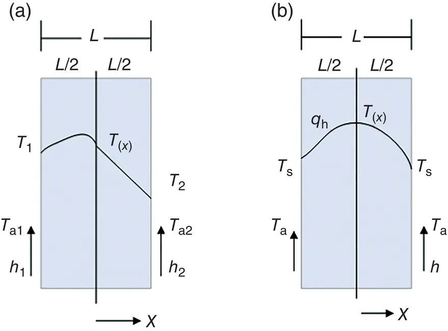
Figure 1.20 Heat conduction in a slab with uniform heat generation: (a) asymmetrical boundary conditions, (b) symmetrical boundary conditions.
At the plane of symmetry d T /d x = 0, and the maximum temperature at the midplane is
(1.117) 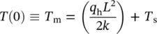
After combining Eqs. (1.116)and (1.117), we find the dimensionless temperature as follows:
(1.118) 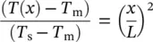
(b) The Cylinder
Consider a long cylinder ( Figure 1.18) with uniform heat generation. The heat conduction equation can be rewritten as
(1.119) 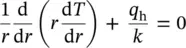
By integrating Eq. (1.119), with the boundary conditions, d T /d r = 0, for the centerline ( r = 0) and T ( r 1) = T s, the temperature distribution can be obtained as
Читать дальшеИнтервал:
Закладка:
Похожие книги на «Thermal Energy Storage Systems and Applications»
Представляем Вашему вниманию похожие книги на «Thermal Energy Storage Systems and Applications» списком для выбора. Мы отобрали схожую по названию и смыслу литературу в надежде предоставить читателям больше вариантов отыскать новые, интересные, ещё непрочитанные произведения.


Обсуждение, отзывы о книге «Thermal Energy Storage Systems and Applications» и просто собственные мнения читателей. Оставьте ваши комментарии, напишите, что Вы думаете о произведении, его смысле или главных героях. Укажите что конкретно понравилось, а что нет, и почему Вы так считаете.