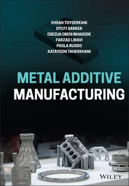
Ehsan Toyserkani - Metal Additive Manufacturing
Здесь есть возможность читать онлайн «Ehsan Toyserkani - Metal Additive Manufacturing» — ознакомительный отрывок электронной книги совершенно бесплатно, а после прочтения отрывка купить полную версию. В некоторых случаях можно слушать аудио, скачать через торрент в формате fb2 и присутствует краткое содержание. Жанр: unrecognised, на английском языке. Описание произведения, (предисловие) а так же отзывы посетителей доступны на портале библиотеки ЛибКат.
- Название:Metal Additive Manufacturing
- Автор:
- Жанр:
- Год:неизвестен
- ISBN:нет данных
- Рейтинг книги:5 / 5. Голосов: 1
-
Избранное:Добавить в избранное
- Отзывы:
-
Ваша оценка:
- 100
- 1
- 2
- 3
- 4
- 5
Metal Additive Manufacturing: краткое содержание, описание и аннотация
Предлагаем к чтению аннотацию, описание, краткое содержание или предисловие (зависит от того, что написал сам автор книги «Metal Additive Manufacturing»). Если вы не нашли необходимую информацию о книге — напишите в комментариях, мы постараемся отыскать её.
A comprehensive review of additive manufacturing processes for metallic structures Metal Additive Manufacturing
Metal Additive Manufacturing
Metal Additive Manufacturing — читать онлайн ознакомительный отрывок
Ниже представлен текст книги, разбитый по страницам. Система сохранения места последней прочитанной страницы, позволяет с удобством читать онлайн бесплатно книгу «Metal Additive Manufacturing», без необходимости каждый раз заново искать на чём Вы остановились. Поставьте закладку, и сможете в любой момент перейти на страницу, на которой закончили чтение.
Интервал:
Закладка:
9 Chapter 12Table 12.1 Related potential hazards by metal AM process category [3].Table 12.2 Different K stvalues for different materials and their severity.Table 12.3 National Fire Protection Association (NFPA) standards [13].
List of Illustrations
1 Chapter 1 Figure 1.1 Global public interest trends for “3D Printing”. Figure 1.2 AM chain, enabling physical parts from digital design. Figure 1.3 Complex parts made by AM. The spherical nest has three spheres in... Figure 1.4 Lightweight structure made by AM. In this typical bracket, the we... Figure 1.5 Consolidation of around 300 parts to one part printed by AM. Figure 1.6 Functionally graded materials (FGMs); (a) Laser DED with multiple... Figure 1.7 A fiber optic embedded in a metallic cutting part using a combine... Figure 1.8 A mold insert with (a) conformal cooling channels, (b) conformal ... Figure 1.9 LDED used to rebuild turbine blades. Figure 1.10 Total AM market size by segment that includes all technologies (... Figure 1.11 Metal AM market size in AMPower Report. Figure 1.12 Timeline for adopted, emerging, and future applications of AM. Figure 1.13 Most important metal AM processes versus part size, complexity, ... Figure 1.14 (a) Dental crowns printed by LPBF(b) joint implants printed ... Figure 1.15 LPBF‐made combustion chamber (left) and the engine in finished c... Figure 1.16 Small‐size, lightweight, one‐piece, AM‐made antenna. Figure 1.17 Hydraulic parts made for the oil and gas industry. Figure 1.18 (a) Ford's custom anti‐theft wheel lock being printed in EOS PBF... Figure 1.19 MX3D smart bridge (a) main structure (b) side wall. Figure 1.20 (a) Three different geometries made of Ti‐6Al‐4V by different pr...
2 Chapter 2 Figure 2.1 Schematic of (a) LPBF and (b) EB‐PBF. Figure 2.2 A view of melt pool and ejected spatters in LPBF. Figure 2.3 Samples of metal parts made via PBF for (a) aerospace, (b) toolin... Figure 2.4 The CT scan results of (i) cylindrical, (ii) triangular prism, an... Figure 2.5 Schematics of (a) powder‐fed laser DED with lateral nozzle(b)... Figure 2.6 Applications of DED: (a) Near‐net‐shape production.(b) Freefo... Figure 2.7 A sample of repaired rotating part using Optomec® LENS DED system... Figure 2.8 A schematic of binder jetting technology. Figure 2.9 ExOne binder jetting technology in Action. Figure 2.10 HP multi‐jet fusion technique steps. Figure 2.11 Sample part made using BJ technology. Figure 2.12 Comparison of traditional binder jetting and Desktop Metal's bin... Figure 2.13 Schematic of material extrusion system. Figure 2.14 A sample metal filament from Desktop Metal. In contrast to polym... Figure 2.15 Visual prototypes made using (a) 17‐4 PH stainless steel on Mark... Figure 2.16 Schematic of material jetting technology. Figure 2.17 XJET's NanoParticle Jetting technique is one of the emerging met... Figure 2.18 Sample parts made using XJET system. Figure 2.19 Ultrasonic consolidation mechanism. Figure 2.20 FGM parts made using Fabrisonic's ultrasonic consolidation syste... Figure 2.21 Process design parameters for LDED, LPBF, and BJ techniques. Figure 2.22 Melt pool and clad/track bead geometrical parameters. Figure 2.23 Relative density vs. energy for various ferrous alloys (a) relat... Figure 2.24 Normalized density vs. specific energy techniques. Figure 2.25 Common scanning strategies. Figure 2.26 (a) Keyhole porosity and its formation mechanism.(b) Lack of... Figure 2.27 The combined effect of scanning velocity and beam power on the d... Figure 2.28 The relationship between melt‐pool geometry and hatching distanc... Figure 2.29 Porosity of LPBF‐made parts from AlSi10Mg as a function of hatch... Figure 2.30 Classification of powder particle properties. Figure 2.31 The relationship between particle and flow properties and flowab... Figure 2.32 Different wire‐feeding orientations. Figure 2.33 Illustration of the staircase effect. Figure 2.34 The maximum layer thickness as a measure of the overlap height o... Figure 2.35 Cross section of a part as the print layer: contour/skin and cor... Figure 2.36 (a, b) Illustration of up‐skin vs down‐skin in PBF process.(... Figure 2.37 The concept of supports structures, three different support shap...Figure 2.38 Printability of the fluids based on dimensionless Reynolds and W...Figure 2.39 The effects of (a) undersaturation and (b) oversaturation on BJ‐...Figure 2.40 H13 tool steel powder agglomeration as a result of oversaturatio...
3 Chapter 3Figure 3.1 Laser powder bed fusion system (LPBF).Figure 3.2 Laser Powder‐Fed (LPF) system.Figure 3.3 Schematic of a binder jetting system setup.Figure 3.4 Illustration of the absorption, spontaneous emission, and stimula...Figure 3.5 Two‐level system scheme.Figure 3.6 A three‐level system scheme.Figure 3.7 Scheme of a four‐level system.Figure 3.8 The main components of a laser are shown. The active medium or ga...Figure 3.9 Solid‐state Laser scheme.Figure 3.10 Energy‐level diagram for Nd3+ doped in YAG.Figure 3.11 (a) Longitudinally excited and (b) transversely excited CO 2lase...Figure 3.12 Laser transitions between vibrational levels in CO 2.Figure 3.13 Liquid dye laser schematic.Figure 3.14 Diode laser scheme.Figure 3.15 Scheme of a typical fiber laser.Figure 3.16 Schematic of fiber lasers that include FBGs and beam couplerFigure 3.17 Energy‐level diagram of the erbium‐doped fiber.Figure 3.18 Laser employed in laser‐based AM processes (i.e. laser powder be...Figure 3.19 Mode patterns for different TEMs.Figure 3.20 Laser beam profile.Figure 3.21 Schematic of a typical EBM apparatus.Figure 3.22 Electron beam formation schematic.Figure 3.23 Gun electrode types: (a) Tungsten (W) filament, (b) Lanthanum He...Figure 3.24 Electromagnetic Lens.Figure 3.25 Scheme of a mechanical wheel powder feeder.Figure 3.26 Schematic of gravity‐based powder feeders with a rotating wheel ...Figure 3.27 Schematic of gravity‐based powder feeders with a metering wheel....Figure 3.28 Schematic of gravity‐based powder feeders with a lobe gear.Figure 3.29 Schematic of a fluidized bed powder feeder.Figure 3.30 Schematic of a vibratory‐based powder feeder.Figure 3.31 Schematic of a typical lateral nozzle.Figure 3.32 Powder feed profile characteristics.Figure 3.33 Schematic of a typical coaxial nozzle.Figure 3.34 Powder stream at the nozzle exit to a co‐axial nozzle.Figure 3.35 Illustration of a LPBF process system setup.Figure 3.36 Schematic of a lateral wire‐feed system equipped with EBM.Figure 3.37 Schematic of a coaxial wire‐feed system.Figure 3.38 Schematic of a galvo scanner.Figure 3.39 Schematics of (a) piezo and (b) thermal inkjet print heads.Figure 3.40 Typical STL file.
4 Chapter 4Figure 4.1 Interaction of a moving heat source and a substrate and the assoc...Figure 4.2 Schematic of phases formed in a mild steel substrate while being ...Figure 4.3 Sinusoidal electromagnetic laser beam: emitted beam, reflected be...Figure 4.4 Graphical concept of the thermal time constant.Figure 4.5 Laser pulse shaping, including pulse width W , pulse energy E , and...Figure 4.6 A typical modulated/pulsed laser beam with rising time, falling t...Figure 4.7 Dependencies of reflectivity to wavelengths, (a) from 200 to 1000...Figure 4.8 Temperature dependencies of reflectivity for Al, Cu, and steel at...Figure 4.9 Dependencies of reflectivity to the angle of incidence for s ‐ray ...Figure 4.10 E‐beam interaction with a substrate and the associated signals g...Figure 4.11 Penetration depth versus absorption coefficient for accelerated ...Figure 4.12 Power density and interaction time for various heat source‐based...Figure 4.13 Schematic of physical domains of DED.Figure 4.14 Track cross section created by DED, (a) high dilution, well wett...Figure 4.15 Dynamic and equilibrium wetting angles.Figure 4.16 A schematic of the process zone during LDED powder‐fed. Melting ...Figure 4.17 Geometry and boundary conditions for a typical coaxial nozzle ex...Figure 4.18 Schematic of 3D heat flow during DED used for the development of...Figure 4.19 Balance of energy in PF‐LDED.Figure 4.20 Lumped cross section of single track deposited in LDED.Figure 4.21 Attenuated laser volume in PF‐LDED.Figure 4.22 Lumped temperature distribution at y = 0 for parameters listed i...Figure 4.23 Schematic diagram for laser powder‐fed laser‐directed deposition...Figure 4.24 Inconel 625 powder stream grayscale intensity distribution measu...Figure 4.25 Schematic diagram for melt pool geometry and deposited track [27...Figure 4.26 Schematic diagram of the solidification front in the longitudina...Figure 4.27 Laser beam intensity distribution on the substrate surface: (a) ...Figure 4.28 Melt pool temperature distribution on Inconel 625 substrate surf...Figure 4.29 Real‐time melt pool top surface peak temperature of SS 316L depo...Figure 4.30 Melt pool peak temperature map for SS 316L single‐track depositi...Figure 4.31 Real‐time local thermal profiles at different clad height locati...Figure 4.32 Effect of G and R on the mode and scale of solidification micros...Figure 4.33 Predicted in situ solidification characteristics at different me...Figure 4.34 Schematic of the laser beam, powder stream and substrate interac...Figure 4.35 Sequence of calculation in the proposed numerical model [37]....Figure 4.36 Maximum temperatures for each layer, when  = 2 g/min, U = 1.5 m...Figure 4.37 Temperature distribution for the second layer deposition at t = ...Figure 4.38 Energy transformations within the deposition area of a substrate...Figure 4.39 Deposition patterns in wire‐fed EBAM.Figure 4.40 Proposed Hammerstein–Wiener nonlinear structureFigure 4.41 Experimental data: (a) multistep process speed and (b) clad/depo...Figure 4.42 Verification of Hammerstein–Wiener dynamic model using unseen da...
Интервал:
Закладка:
Похожие книги на «Metal Additive Manufacturing»
Представляем Вашему вниманию похожие книги на «Metal Additive Manufacturing» списком для выбора. Мы отобрали схожую по названию и смыслу литературу в надежде предоставить читателям больше вариантов отыскать новые, интересные, ещё непрочитанные произведения.
Обсуждение, отзывы о книге «Metal Additive Manufacturing» и просто собственные мнения читателей. Оставьте ваши комментарии, напишите, что Вы думаете о произведении, его смысле или главных героях. Укажите что конкретно понравилось, а что нет, и почему Вы так считаете.
