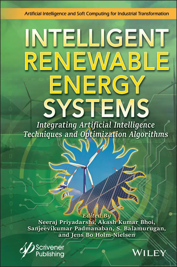
Intelligent Renewable Energy Systems
Здесь есть возможность читать онлайн «Intelligent Renewable Energy Systems» — ознакомительный отрывок электронной книги совершенно бесплатно, а после прочтения отрывка купить полную версию. В некоторых случаях можно слушать аудио, скачать через торрент в формате fb2 и присутствует краткое содержание. Жанр: unrecognised, на английском языке. Описание произведения, (предисловие) а так же отзывы посетителей доступны на портале библиотеки ЛибКат.
- Название:Intelligent Renewable Energy Systems
- Автор:
- Жанр:
- Год:неизвестен
- ISBN:нет данных
- Рейтинг книги:5 / 5. Голосов: 1
-
Избранное:Добавить в избранное
- Отзывы:
-
Ваша оценка:
Intelligent Renewable Energy Systems: краткое содержание, описание и аннотация
Предлагаем к чтению аннотацию, описание, краткое содержание или предисловие (зависит от того, что написал сам автор книги «Intelligent Renewable Energy Systems»). Если вы не нашли необходимую информацию о книге — напишите в комментариях, мы постараемся отыскать её.
This collection of papers on artificial intelligence and other methods for improving renewable energy systems, written by industry experts, is a reflection of the state of the art, a must-have for engineers, maintenance personnel, students, and anyone else wanting to stay abreast with current energy systems concepts and technology.
Audience
Intelligent Renewable Energy Systems — читать онлайн ознакомительный отрывок
Ниже представлен текст книги, разбитый по страницам. Система сохранения места последней прочитанной страницы, позволяет с удобством читать онлайн бесплатно книгу «Intelligent Renewable Energy Systems», без необходимости каждый раз заново искать на чём Вы остановились. Поставьте закладку, и сможете в любой момент перейти на страницу, на которой закончили чтение.
Интервал:
Закладка:
7 Chapter 7Figure 7.1 Block diagram of FLC based energy management unit (EMU) for stand-alo...Figure 7.2 Equivalent circuit for PV.Figure 7.3 Solar arrays.Figure 7.4 Optimal torque control with MPPT method.Figure 7.5 Battery equivalent circuit.Figure 7.6 Developed FLC based energy management unit.Figure 7.7 Graph, PV system with irradiance change from 600W/m 2to 800W/m 2, 800W...Figure 7.8 Graph of Input wind speed change from 12m/s to 8m/s, 8m/s to 10m/s wa...Figure 7.9 Graphed results for battery system, waveforms.Figure 7.10 Simulation results for EMU, waveform of (a) battery Vref & Vdcbus (v...Figure 7.11 Power levels of load, battery, wind and solar system.
8 Chapter 8Figure 8.1 Time-varying characteristics of (a) Active and (b) Reactive power dem...Figure 8.2 Standard deviation and Mean of the wind speed.Figure 8.3 Power output of WTDG for different times of the day.Figure 8.4 Membership functions for (a) SVEI , (b) EFI and (c) ECRI .Figure 8.5 Flow chart of the proposed approach.Figure 8.6 Schematic representation of the modified 33-bus system.Figure 8.7 (a) Active and (b) Reactive power loss for different planning stages.Figure 8.8 Bus voltages of the test network in (a) Scenario 1 and (b) Scenario 2...Figure 8.9 Power flow in the test network for planning (a) case 1, (b) case 2 an...Figure 8.10 Power flow in the test network for planning (a) case 1, (b) case 2 a...Figure 8.11 Convergence characteristic for all techniques for (a) Planning case ...
9 Chapter 9Figure 9.1 Block diagram of a stand-alone PV system.Figure 9.2 Schematic diagram of a grid-tied PV system.Figure 9.3 Block diagram of a large PV system.Figure 9.4 Flowchart for GUI design.Figure 9.5 GUI front end for the design of a standalone PV system using sample h...Figure 9.6 GUI front end for design of a grid-tied PV system for a rooftop area ...Figure 9.7 GUI front end for design of a PV power plant for an available land ar...
10 Chapter 10Figure 10.1 Micro-grid with micro-PMU.Figure 10.2 Micro PMU block diagram.Figure 10.3 Situational awareness.Figure 10.4 Connection diagram of micro-PMU.Figure 10.5 Flow chart of (a) comprehension algorithm (b) LVQ algorithm.Figure 10.6 LVQ algorithm LabVIEW program.
11 Chapter 11Figure 11.1 Basic structure of ES.Figure 11.2 ANN architecture of BPA.Figure 11.3 Functional block diagram of Fuzzy Inference System.Figure 11.4 Communication architecture of HEMS.Figure 11.5 Overall STLF procedure based on RL and BPNN.Figure 11.6 Centralized generation system.Figure 11.7 Structure of distributed generation system.Figure 11.8 Structure of LET.Figure 11.9 Operation of AI-SEM.
12 Chapter 12Figure 12.1 Single line diagram of n -node RDN.Figure 12.2 Flowchart of the proposed loss allocation algorithm.Figure 12.3 Total energy losses in the network at 1-h interval for scenario with...
13 Chapter 13Figure 13.1 Schematic and equivalent circuit of STATCOM.Figure 13.2 Type-2 controller for 2-level VSC based STATCOM.Figure 13.3 Movement of the critical eigenvalues with PI controller for kp = 0 t...Figure 13.4 Step response of STATCOM with PI controller.Figure 13.5 PI controller with nonlinear feedback controller.Figure 13.6 Root locus with nonlinear feedback for kp = 0 to 10 and ki / kp = 10.Figure 13.7 Phase ‘a’ current of STATCOM with nonlinear feedback controller.Figure 13.8 Response of STATCOM with nonlinear feedback controller.Figure 13.9 Schematic of type1controller for STATCOM.Figure 13.10 Step response with 3phase model of STATCOM with non-optimized contr...Figure 13.11 D-contour with α = −0.5 and ζ = 10%.Figure 13.12 Phase ‘a’ current of STATCOM with optimal controller parameters.Figure 13.13 Step response with 3-phase model of STATCOM and optimal controller ...Figure 13.14 Location of eigenvalues of STATCOM with optimal controller paramete...Figure 13.15 Step response with 3-phase model of STATCOM with optimal controller...Figure 13.16 Phase ‘a’ current of STATCOM with optimal controller parameters.Figure 13.17 Value of objective function at every function evaluation and iterat...Figure 13.18 Value of objective function at every function evaluation and iterat...Figure 13.19 Best value of objective function at every iteration with GA and PSO...Figure 13.20 Time for iteration with GA and PSO.Figure 13.21 Best value of objective function for ten continuous runs of GA and ...Figure 13.22 Plot of eigenvalues from maximum capacitive to inductive operation ...Figure 13.23 Phase ‘a’ current of STATCOM with optimal controller parameters.Figure 13.24 Step response with three phase model of STATCOM and optimal control...Figure 13.25 System diagram of VSC HVDC.Figure 13.26 Equivalent circuit of VSC viewed from ac bus.Figure 13.27 Controller for one of the VSCs of HVDC.Figure 13.28 Step response 3-level VSC HVDC with non-optimized controller parame...Figure 13.29 Step response 3-level VSC HVDC with non-optimized controller parame...Figure 13.30 Step response of reactive current, power and DC voltage for case-1 ...Figure 13.31 Step response of power and DC voltage for case-2 with optimal contr...Figure 13.32 Step response of reactive current, power and DC voltage for case-3 ...Figure 13.33 Step response of power and DC voltage for case-4 with optimal contr...Figure 13.36 Step response of power and DC voltage for case-7 with optimal contr...Figure 13.37 Step response of power and DC voltage for case-8 with optimal contr...Figure 13.34 Step response of reactive current, power and DC voltage for case-5 ...Figure 13.35 Step response of power and DC voltage for case-6 with optimal contr...
14 Chapter 14Figure 14.1 Combined cycle power plant.Figure 14.2 Block diagram of ANN structure.Figure 14.3 Neural network model.Figure 14.4 Regression plot.Figure 14.5 Performance plot.Figure 14.6 Error Histogram.Figure 14.7 Training state plot.Figure 14.8 Forecast results for the month of March.
15 Chapter 15Figure 15.1 Basic work model of global aggregator (GA).Figure 15.2 Proposed charging scheme cycle.Figure 15.3 Flowchart of scenario 1.Figure 15.4 Flowchart of scenario 2.Figure 15.5 Fitting result of on time arrival.Figure 15.6 Fitting result of late arrivals.Figure 15.7 Fitting result of daily driving distance.Figure 15.8 SUV’s average waiting time in both scenarios.Figure 15.9 Hatchback’s average waiting time in both scenarios.Figure 15.10 Total charged hatchback in both scenarios.Figure 15.11 Total charged SUV in both scenarios.
List of Tables
1 Chapter 1 Table 1.1 CEC 2005 benchmark function [67]. Table 1.2 Parameters of different algorithms for benchmark functions. Table 1.3 Optimization result of CEC-2005 benchmark functions. Table 1.4 Variation of load demand (pu) and solar power generation (pu) with loa... Table 1.5 Cost and lifetime of different DGs. Table 1.6 Optimum placement of RDGs and shunt capacitors to the 33-bus distribut... Table 1.7 Optimum placement of RDGs and shunt capacitors to the 69-bus distribut...
2 Chapter 2 Table 2.1 List of one-dimensional chaotic maps. Table 2.2 Unimodal and multimodal test problems and their details. Table 2.3 Results of the test problems with the proposed methods.Table 2.4 Non-parametric test outcomes (part-1).Table 2.5 Non-parametric test outcomes (part-2).Table 2.6 Datasheet values of PV modules at STC conditions.Table 2.7 Estimated parameters of the three-diode model for Kyocera (KC200GT mul...Table 2.8 Optimal parameter identification of the three-diode model for Canadian...Table 2.9 Normalized statistical analysisof the error function for the three-dio...Table 2.10 Normalized results of the sum of square error (SSE) for the three-dio...
3 Chapter 3Table 3.1 Comparison of machine learning and artificial intelligence based islan...
4 Chapter 4Table 4.1 Rule base for fuzzy logic controller.
Читать дальшеИнтервал:
Закладка:
Похожие книги на «Intelligent Renewable Energy Systems»
Представляем Вашему вниманию похожие книги на «Intelligent Renewable Energy Systems» списком для выбора. Мы отобрали схожую по названию и смыслу литературу в надежде предоставить читателям больше вариантов отыскать новые, интересные, ещё непрочитанные произведения.


Обсуждение, отзывы о книге «Intelligent Renewable Energy Systems» и просто собственные мнения читателей. Оставьте ваши комментарии, напишите, что Вы думаете о произведении, его смысле или главных героях. Укажите что конкретно понравилось, а что нет, и почему Вы так считаете.